
本文有中文翻译版本:高压增强隔离:定义和测试方法
Understanding the definitions of high-voltage isolation parameters, their relevance to real applications, and the methodologies used to test them, allows systems engineers to pick the right isolator for their design need.
Designing systems involving high voltage and high-voltage isolation is complicated.
How much isolation do I need in my system? What system level isolation standards apply to my product or end equipment? Are there component-level standards that help me compare between isolators, and choose the one that best fits my system level need? Which parameters or metrics should I compare – there seem to be many? What are the test procedures that isolation components go through to support the parameters in their datasheets? And foremost, how do I make sure that I am building a system that ensures reliable operation throughout my product’s lifetime? These are questions faced by many systems engineers dealing with high voltage and high-voltage isolation.
Isolation is a means of preventing DC and unwanted AC currents between two parts of a system, while allowing signal and power transfer between those two parts. Electronic devices and semiconductor ICs used for isolation are called isolators. Isolation is required in modern electrical systems for a variety of reasons. Some examples are to prevent electrical shock to human operators and preventing damage to expensive processors, ASICs or FPGAs in high-voltage systems, breaking the ground loop in communication networks and communication to high-side devices in motor drive or power converter systems. Examples of applications that need isolation include industrial automation systems, motor drives, medical equipment, solar inverters, power supplies and hybrid electric vehicles (HEV).
When isolation is used to enable the system to function properly, but not necessarily to serve as a barrier against shock, it is called functional isolation. Where isolation provides sufficient protection against electrical shock as long as the insulation barrier is intact, it is called basic isolation. Safety regulations require basic isolation to be supplemented with a secondary isolation barrier for redundancy, so that the additional barrier provides shock protection, even if the first barrier fails. This is called double isolation. To make systems compact and save cost, it is desirable to have only one level of isolation that has the required electrical strength, reliability, and shock protection of two levels of basic isolation. This is called reinforced isolation. High-voltage isolation performance of an isolator is quantified at the component level by parameters such as maximum repetitive peak voltage (VIORM), working voltage (VIOWM), maximum transient isolation voltage (VIOTM), isolation withstand voltage (VISO), maximum surge isolation voltage (VIOSM) and comparative tracking index (CTI) among others. These parameters represent the isolator’s capability to handle high-voltage stresses of different magnitude and transient profiles, and have a direct mapping to realistic operating situations. The definitions and test methodologies for these parameters are described in component-level standards such as IEC 60747-5-5, VDE 0884-10, and UL 1577. Test methodologies differ slightly for basic and reinforced isolators, and are more stringent for the latter. VDE 0884-10 is defined especially for magnetic and capacitive couplers or isolators. When isolators are used in real applications, systems and end equipment standards also mandate certain minimum values of these isolation parameters depending on the system line voltage, and based on whether basic or reinforced isolation is required. IEC 61800-5-1 (safety standard for adjustable speed electrical drives), IEC 60664-1 (insulation coordination for equipment within low voltage systems) and IEC 61010-1 (safety standard for measurement, control, and lab equipment) are examples of systems and end equipment standards. This document discusses, in detail, the definitions of the above mentioned high-voltage Isolation parameters, their relevance to real-life system scenarios, and describes how they are tested and certified. This understanding is essential to compare the performance of competing isolation solutions, to decide whether an isolator meets system-level isolation requirements, to determine if an isolator can be used for reinforced isolation, and to judge the long-term reliability of an isolator. The ISO7842 is a robust electromagnetic compatibility (EMC), high-speed, high common mode transient immunity (CMTI), quad-channel reinforced digital isolator. It uses capacitance-based isolation with silicon-dioxide (SiO2) as the dielectric.
This device uses advanced processing technology, precise packaging technology, and innovative circuit design, to deliver industry-leading high voltage and electrical performance.
This document discusses test procedures and results from high voltage testing on the ISO7842. Test results demonstrate the exceptional high voltage performance and reliability of this device, and enable the system engineer to solve the toughest of isolation problems with confidence.
Maximum transient isolation voltage and isolation withstand voltage
Maximum transient isolation voltage (VIOTM) and the isolation withstand voltage (VISO) are both intended to quantify the ability of an isolator to handle high voltage across the isolation barrier for very short periods of time. During normal operation, the stress voltage across the isolation barrier is limited by the maximum system line voltage. However, unintentional disturbances in the system, for example, noise on the supplies caused by arcing or load changes, could briefly cause the voltage across the isolator to be several times the line voltage. The isolator should be able to handle these transient over-voltages without damage.
VIOTM is defined by IEC 60747-5-5 and VDE 0884-10 as the peak transient voltage that the isolator can handle without breaking down. This is tested during certification by stressing the isolator at VIOTM for 60 seconds, followed by a partial discharge test at 1.6 times VIORM for 10 seconds (see next section for the definition of VIORM). This is called Method A testing.
VIOTM is tested in the production manufacturing process by stressing every device at VIOTM for one second, followed by a partial discharge test at 1.875 times VIORM for one second. This is called Method B1 testing. Partial discharge is localized discharge inside the insulation material and is indicative of insulation integrity. More details on Method A and Method B1 test profiles can be found in the appendix.
The value of VIOTM also can be used to determine compliance to system-level standards, such as the IEC 60664-1, that require a certain level of temporary overvoltage to be tolerated by an insulation barrier, for five seconds, depending on the system voltage. For example, an isolator with a VIOTM of greater than 6222 Vpk (4400 Vrms) meets the temporary overvoltage criterion for reinforced insulation per IEC 60664-1 for line voltages up to 1000 Vrms. VISO is defined per UL 1577 as the rms value of voltage that the isolator can handle without breakdown for 60 seconds. It is tested during certification by applying a sinusoidal stress of VISO for 60 seconds. In production VISO is tested by stressing every device for 1.2 times VISO for one second. For sinusoidal stress VIOTM and VISO are equivalent. TI tests its digital isolators to comply with UL, IEC, and VDE requirements. To perform testing for VIOTM or VISO, an HT9464 high-voltage isolation test system is used. This equipment is capable of applying the required transient overvoltage profile according to Method A and Method B1, as well as measuring partial discharge. This test is performed by connecting all pins of side one and all pins of side two, then applying the voltage across the isolation barrier (Figure 1).
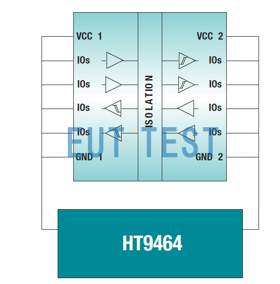
Figure 1: HT9464 Test setup for testing VIOTM and VISO
The ISO7842 meets a VISO of 5700 Vrms per UL and a VIOTM of 8000 Vpk per VDE0884-10 and IEC 60747-5-5. This is based on Method A testing over more than five wafer lots, and a total of more than 2000 devices. Also, each and every ISO7842 device will be production-tested per Method B1, with the stress voltage greater than 6840 Vrms to meet UL requirements. These levels of VISO and VIOTM are the highest offered by any isolator in the industry in a standard 16-pin SOIC package.
It must be noted that ISO7842 easily meets the 4400 Vrms requirement for temporary overvoltage required for reinforced isolation as per IEC 60664-1 for line voltages up to 1000 Vrms.
Maximum repetitive peak voltage and working voltage
Maximum repetitive (VIORM) and working voltage (VIOWM) are both intended to quantify the ability of an isolator to handle high voltage across its barrier on a continuous, day-to-day basis, throughout its lifetime.
For example, an isolator used to provide gate control to a high-side IGBT in a motor drive system sees a periodic trapezoidal potential difference across its isolation barrier as the IGBT emitter, to which the isolator’s secondary side is referred, moves up and down between high-voltage dc rails. This trapezoidal stress is present whenever the motor is operational. VIORM and VIOWM are defined in IEC 60747-5-5 and VDE 0884-10. VIORM is defined as the maximum repetitive peak voltage that the isolator can withstand, whereas VIOWM is defined as the maximum rms, or equivalent dc voltage, that the isolator can withstand over a specified long term. For sinusoidal stress voltages, VIORM and VIOWM are equivalent. Both values are specified by the manufacturer of the isolator based on the manufacturer’s testing.
VDE 0884-10 Ed 1.0 and IEC 60747-5-5 check for VIOWM and VIORM through a partial discharge test that looks for localized discharges inside the insulation that indicate degradation in the insulation. The partial discharge test is performed along with the test for VIOTM using Method A tests during certification and Method B1 during production test. The soon to be released VDE 0884-10 Ed 2.0 also includes an additional requirement on VIORM and VIOWM. To comply with this new upcoming standard, the manufacturer of a reinforced isolator must provide accelerated-stress test data to the certifying agencies to prove that the isolator can handle 1.2 times VIOWM/VIORM for more than 37.5 years. During accelerated-stress tests, the isolator is subjected to varying levels of high voltage, much higher than its expected working voltage, and the corresponding times to breakdown are recorded. Then, the voltage vs. time curve is extrapolated for lifetime prediction at the expected working voltage. For isolators that use silicon-dioxide (SiO2) as the insulation material, the relation between time-to-failure and stress voltage follows an exponential relationship. Consequently, the log of expected time to failure reduces linearly with voltage stress applied. Therefore, VDE 0884-10 Ed 2.0 requires SiO2-based isolators to use the same relation to curve-fit accelerated test data.
Figure 2 shows the test setup used to perform accelerated-stress lifetime tests. All terminals on side one of the isolators are shorted together, and all terminals of side two of the isolator are shorted together. The required high voltage, a 60 Hz sine wave, is applied between sides one and two to stress the isolation barrier using a high-voltage source such as the AR7715 High pot. The stress voltage is applied continuously until the impedance between side one to side two drops below 4 MΩ. At each voltage point, batches of at least 32 devices are stressed. The resulting times to failure of the devices are fit to a Weibull distribution, and statistical analysis is used to find the time to failure that corresponds to <1 ppm failure rate. This time is then plotted in the voltage vs. time to failure plot. The procedure is repeated at different voltage points to generate the entire voltage vs time to failure curve. This curve, when extrapolated to greater than 37.5 years, and further de-rated by an extrapolation factor of 1.2, gives the value of VIOWM/VIORM. For a more comprehensive understanding of the accelerated stress test and the related extrapolation, refer to the VDE 0884-10 Ed 2.0 standard. An accelerated-stress test is performed both at high temperature (150°C) as well as room temperature(25°C). The values of VIORM and VIOWM derived from accelerated stress tests, as mandated by VDE 0884-10 Ed 2.0, give more confidence in the long-term reliability of the isolator for continuously applied high voltage. The same cannot be said about the partial discharge test mandated by IEC 60747-5-5 and VDE 0884-10 Ed 1.0, since there is no established relationship between long-term withstand capability and partial discharge.
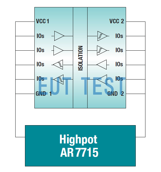
Figure 2: Setup for accelerated-stress lifetime tests.
Figure 3 shows the expected lifetime projection of the ISO7842 based on accelerated-stress testing of the isolation barrier used over five different wafer lots and a total of more than 2000 devices. The shaded region indicates the safe operating area (SOA) of this device. Note that the actual test data is intentionally not shown in the figure. The SOA includes a factor of 1.2 de-rating as required by the standard and is also based on a more conservative statistical extrapolation than required by the standard. The SOA can be used to estimate the expected lifetime at any given operating voltage.
The <<1 ppm line indicates that much less than one device in one million is expected to lie outside the SOA. As shown in the SOA curve of Figure 3, the ISO7842 can withstand a VIORM of 2121 Vpk and a VIOWM of 1500 Vrms for more than 40 years. These levels of VIORM and VIOWM are the highest offered by any isolator in the industry, in a standard 16-pin SOIC package.
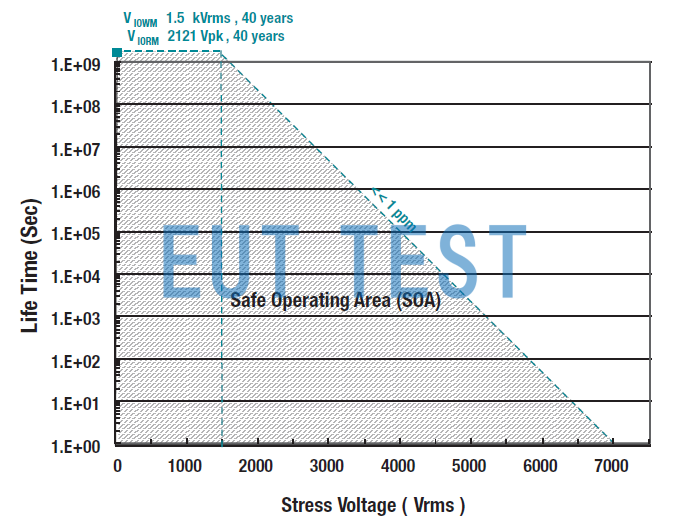
Figure 3: ISO7842 lifetime versus stress voltage.
Maximum surge isolation voltage
Maximum surge isolation voltage (VIOSM) quantifies the ability of the isolator to withstand very high voltage impulses of a certain transient profile. The surge test profile is shown in Figure 4. Surge voltages can be caused in an installation due to direct or indirect lightning strikes, faults, and short circuit events. As per IEC 60747-5-5 and VDE 0884-10, an isolator claiming a certain VIOSM must pass the surge test at a peak voltage of 1.3 times VIOSM for basic isolation, and 1.6 times VIOSM for reinforced isolation. An isolator can be called reinforced at the component level, only if it passes the surge test at a level greater than 10 kV. The passing level of a surge test is also used to determine compliance to system-level standards, such as the IEC 61800-5-1, that require a certain level of surge capability for a given system voltage.
For example, for equipment connected directly to supply mains (known as category III), operating at 600 Vrms line voltages, IEC 61800-5-1, requires a minimum surge capability of 8000 V for reinforced isolation.
Note that passing a surge test at levels greater than 10 kV has been widely used as the gold standard for reinforced isolation, though system level standards allow for lower values of surge capability for systems with lower line voltages.
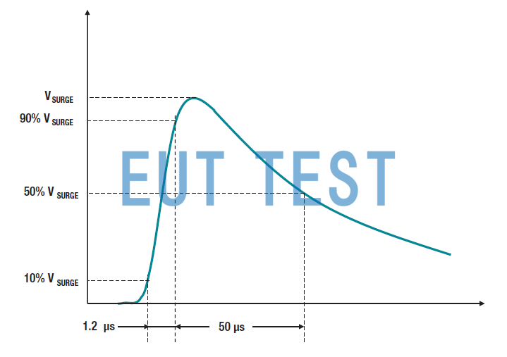
Figure 4: Surge impulse profile.
Figure 5 shows the setup used to test surge performance on the ISO7842. The isolator is configured as a two-terminal device by shorting all the left-side pins to one group, and all right-side pins to another group. Surge voltage is applied across the isolation barrier using either the MIG1203 or the MIG2403 surge generators, depending on the test voltage required.
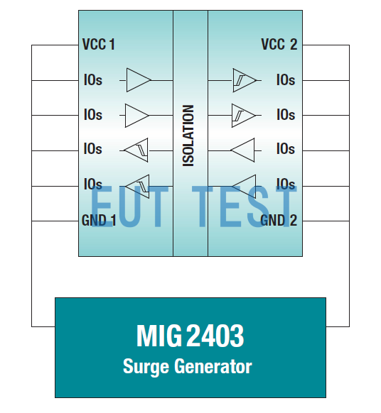
Figure 5: Surge test setup.
The test is performed by applying 50 pulses each for both positive and negative polarities of the rated stress voltages. After the surge test, a partial discharge test per method B1, insulation impedance test and a full functional production test are performed on the device. A device is considered to pass the surge test if it successfully passes all these tests after applying the surge voltage. To avoid arcing through the air, this test is performed in dielectric oil. Based on testing on greater than five wafer lots, and a total of more than 2000 devices, the ISO7842 passes the surge voltage test at greater than 12800 V. Since this exceeds 10 kV, it meets the limit for reinforced isolators. The rated value of VIOSM is 8000 V, according to the scaling factor of 1.6 required for reinforced isolation. Passing a 12800 V surge test also implies that this device meets the surge criterion for reinforced isolation for equipment connected directly to supply main, for line voltages up to 1000 Vrms, as per IEC 61800-5-1.
Comparative tracking index
When an isolator is placed on a system board as part of end equipment in addition to its internal isolation parameters, the mold compound used in its package is important. This is because when high voltage is applied across the isolator, electric discharges on or close to the surface of the package, can cause localized deterioration in the mold compound, resulting in a partially conducting path from one side of the isolator to the other. This phenomenon is called tracking. The ability of a material to withstand tracking is quantified by a comparative tracking index (CTI).
IEC 60664-1 classifies materials into four material groups according to their CTI values:
<<<<提醒:左右滑动表格>>>>| Material group I: | 600 V < CTI |
| Material group II: | 400 V < CTI < 600 V |
| Material group IIIa: | 175 V < CTI < 400 V |
| Material group IIIb: | 100 V < CTI < 175 V |
CTI plays a major role in determining the minimum creepage, or shortest distance along the surface of the isolator from pins on one side of the isolator to pins on the other side. A minimum creepage is required for a given working voltage depending on the extent of the pollution present in the system environment. Using a mold compound with a higher CTI allows the use of smaller packages, and saves board space. For example, as per IEC 60664-1, a package with 8 mm creepage using a CTI-I mold compound can withstand up to 1600 Vrms of working voltage, whereas the same package using a CTI-IIIa mold compound can withstand only 800 Vrms.
The ISO7842 uses a CTI-I mold compound. This implies that it can actually enable a 1500 Vrms working voltage at the system level with a standard 8 mm creepage SOIC-16 package. In contrast, competing isolators using a CTI-IIIa mold compound in the same package can only enable a working voltage of 800 Vrms at the system level, even though they may claim a higher value of VIORM/VIOWM at the component level.
Distance through insulation
Distance through insulation (DTI) is the smallest distance between the two voltage domains in the isolator internal to the isolation package. Many end-equipment standards such as the IEC 60601-1 (medical electrical equipment standard) specify a minimum required distance through insulation.
However, these standards have provisions that allow thinner insulation layers, provided they pass certain tests. These tests are a subset of the type tests required per VDE 0884-10. Historically, a higher DTI was a direct indication of isolation performance based on the insulation material used. However, due to the new generation of magnetic and capacitive isolators using higher quality insulating materials, a very high isolation performance can be obtained by a much smaller DTI.
The ISO7842 has a minimum internal DTI of 21 μm, with a typical DTI of 25 μm. However, the breakdown strength of the dielectric material used, SiO2, is very high at 800 V/μm. The quality of the dielectric used is the reason for this device’s superior high-voltage performance. This device meets the type test criteria of VDE 0884-10 for reinforced isolation, proving that a DTI of 25 μm using material with 800 V/μm of breakdown strength is not a matter of concern.
Table 1. Performance summary of the ISO7842
<<<<提醒:左右滑动表格>>>>| 序号 | 属性 | 标准 | 值 |
| 1 | Viso | UL1577 | 5700Vrms |
| 2 | Viotm | VDE 0884-10 Ed1.0和Ed2.0 | 8000Vpk |
| 3 | Viorm | VDE 0884-10 Ed1.0和Ed2.0 | 2121 Vpk (>40 years) |
| 4 | Viowm | VDE 0884-10 Ed1.0和Ed2.0 | 1500 Vrms (>40 years) |
| 5 | Viosm | VDE 0884-10 Ed1.0和Ed2.0 | 8000 V (浪涌测试通过电平 >12.8 kV) |
| 6 | CTI | IEC 60664-1 | CTI >600 material group: I |
| 7 | DTI | NA | 21 μm (min) / 25 μm (typ) Note: Breakdown field for SiO2 is 800 V/μm |
Notes:
1. ISO7842 also meets the VISO, VIOTM, VIORM and VIOWM values mentioned in Table 1 per IEC 60747-5-5. However, the ISO7842 will not be certified to IEC 60747-5-5 as that standard is specific to optocouplers and not capacitive couplers.
2. VDE 0884 Ed 2.0 (soon to be released) is a revision of VDE 0884 Ed 1.0. It has tighter constraints and additional requirements over IEC 60747-5-5 and VDE 0884 Ed 1.0 for VIOWM and VIORM.
Conclusions
The high-voltage isolation performance of an isolator is quantified with different parameters, which represent the isolator’s capability to handle high voltage stresses of different magnitude and transient profiles. Various component-level standards define these parameters and the methodologies to test them. This white paper discusses in detail the definitions of these parameters, their relevance to real-life system scenarios, and describes how they are tested and certified.
Results from tests on TI’s ISO7842 reinforced digital isolator, performed according to standard procedures, are presented. This device meets the transient overvoltage and surge requirements for reinforced isolation at both the component and system level, and enables reliable operation for many years in the presence of continuous, high operating voltage. The test results demonstrate that this device marks a significant leap in TI’s capacitive high-voltage isolation capabilities, and at the same time delivers industry-leading, high-voltage performance.
References
1. IEC 60747-5-5 Ed 1.1, Semiconductor devices – Discrete devices – Part 5-5: Optoelectronic devices – Photocouplers, May 2013
2. DIN V VDE V 0884-10 Ed 1.0, Semiconductor devices – Magnetic and capacitive couplers for safe isolation, Dec 2006
3. UL 1577 Ed 4.0, Standard for Safety for Optical Isolators, May 2000
4. IEC 61800-5-1 Ed 2.0, Adjustable speed electrical power drive systems, safety requirements, electrical, thermal and energy, July 2007
5. IEC 60644-1 Ed 2.0, Insulation coordination for equipment within low-voltage systems, principles, requirements and tests, Apr 2007
6. IEC 61010-1 Ed 3.0, Safety requirements for electrical equipment for measurement, control, and laboratory use, general requirements, June 2010
7. ISO7842 product folder
8. ISO7841 product folder
9. ISO7821 product folder
10. Reinforced Isolation meets unmatched performance
11. Sarangan Valavan, Understanding electromagnetic compliance tests in digital isolators,
White Paper, Texas Instruments, November 2014
Appendix
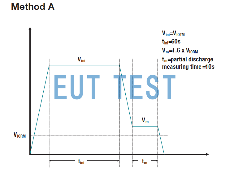
Figure 6: Simplified Method A test profile.
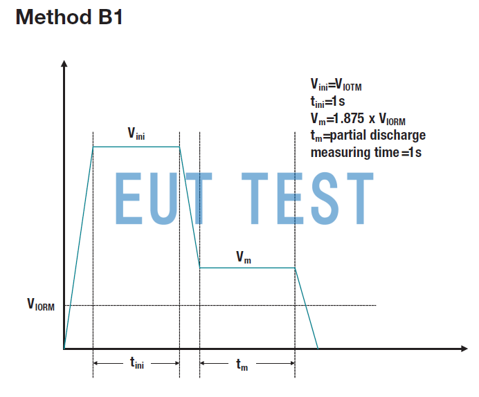
Figure 7: Simplified Method B1 test profile.
Important Notice: The products and services of Texas Instruments Incorporated and its subsidiaries described herein are sold subject to TI’s standard terms and conditions of sale. Customers are advised to obtain the most current and complete information about TI products and services before placing orders. TI assumes no liability for applications assistance, customer’s applications or product designs, software performance, or infringement of patents. The publication of information regarding any other company’s products or services does not constitute TI’s approval, warranty or endorsement thereof. SLYY063A
Author:
Anant S Kamath ,Systems Engineer, Isolation, Interface Group Texas Instruments.
Kannan Soundarapandian, General Manager, Motor Drivers Texas Instruments.