EUTTEST
Shenzhen EUTTEST Technology Co., Ltd.

Langer-emv analog signal to optical fiber signal sensor usage method


The following is the complete usage method of the German langer-emv analog to optical fiber signal sensor to oscilloscope prepared by EUTTEST for you. If you have any questions about this serial product, you can contact EUTTEST for consultation.

Langer-EMV products covered by these instructions:

A100-1 set, A100-2 set;

A200-1 set, A200-2 set;

A300-1 set, A300-2 set;

How to use A200-1/2 analog-to-fiber combo kit:

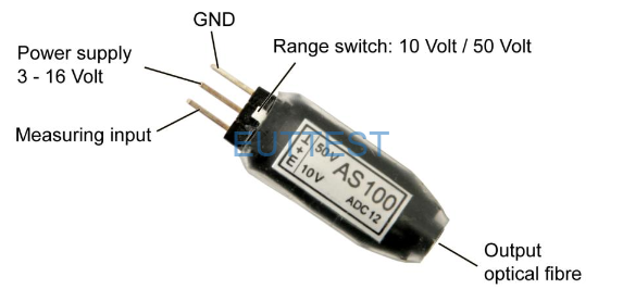
1. Understand the connection diagram of A200-1 analog to optical fiber

A200-1 connection diagram


2. A200-1 connects to the real analog signal

Connect A200-1 to the pin of the IC or component under test, and the analog signal will be converted to an optical signal


3. Connect the tail fiber of A200-1 to the fiber receiver

A200-1 optical signal is transmitted to the receiver and converted back to an analog signal readable by the oscilloscope


4. Connect the optical fiber receiver to the oscilloscope

The oscilloscope shows that the A200-1 obtains an analog signal after photoelectric conversion.


You can also use an analog-to-optical fiber signal sensor to monitor whether a certain pin on the EUT is affected by E1 pulse interference when using the E1 anti-interference development system. After connecting the EUT pin and the oscilloscope according to the above process, use E1 to inject an interference signal at the PCB location of interest.

For more product information, click->E1 anti-interference development system.

AS100 and E1 are used together to detect the pulse interference waveform emitted by E1


Get a preferential offer for this device:

Contact

On the Contact us page, you can view the sales number and fill out the form online.

Related indicators of this equipment:

error:Error type: Copying is prohibited on this page. Contact us for information. Content is protected! !It is forbidden to display on this page. Contact us for more information. The content is protected! !