
Introduction:
The concept of EMC electromagnetic compatibility:
Electromagnetic compatibility (EMC) is the branch of electrical engineering that deals with the unintentional generation, propagation and reception of electromagnetic energy that may have unwanted effects on other working electronic products, such as electromagnetic interference (EMI), or even cause physical damage to other equipment. The purpose of the EMC study is to ensure that all equipment works properly in a common electromagnetic environment.IEC CLC/TC210 Division is the IEC International Electrotechnical Commission's organization responsible for the publication of EMC test standards.
CLC/TC210 is the IEC organization that publishes EMC standards.
Three important factors of electromagnetic compatibility:
The diagram below illustrates the three most important elements in the EMC EMC testing process, each of which must be present, although in general it may not be easy to identify the specific cause. EMC problems are usually solved by identifying at least two of these elements and eliminating (or attenuating) one of them. Interference mitigation can be achieved and thus EMC compliance. By understanding and mastering the three core elements of EMC interference - the source, the coupling path and the receiver - sensitive equipment, we can take more targeted measures to prevent and solve EMC problems and thus improve the performance and stability of electronic equipment to ensure that they can operate reliably in the complex and changing electromagnetic environment.
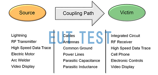
EMC examines three broad categories of issues
First element: source of electromagnetic energy emission EMI - source of interference:
Whether the energy is intentional or accidental, it has a source and is released into the working environment.EMC test standards examine and define the amount of electromagnetic energy emitted and the measures that can be taken to minimize unwanted emissions. In addition, the regulation defines the electrical and electronic products under test, which are generally referred to asEUT object to be measured or DUT object to be measured, so EMC testing can be understood as Eut Test for EMC.
Type of interference source:
Natural sources of interference:
Natural sources of interference refer to various electromagnetic phenomena that exist in nature, such as lightning, sunspot activity, and electrostatic discharges. For example, when lightning occurs, it generates a powerful electromagnetic pulse that may cause interference or even damage to surrounding electronic equipment. Sunspot activity can also cause changes in electromagnetic radiation, affecting the electromagnetic environment on the Earth's surface.
The accumulation of static electricity on the human body and equipment is also a common source of natural interference. When static electricity accumulates to a certain extent, it will release energy in the form of discharge, producing transient electromagnetic interference. For example, when we touch the electronic equipment, sometimes we will feel a slight electric shock brought about by electrostatic discharge, which is a typical phenomenon of electrostatic discharge.
Man-made sources of interference:
Man-made sources of interference, on the other hand, are mainly electromagnetic interference generated by human activities. These sources of interference are widely present in our living and working environments and include, but are not limited to, radio transmitting equipment (e.g., cellular base stations, radio and television towers), industrial equipment (e.g., electric motors, frequency inverters), scientific and medical equipment (e.g., high-frequency scalpels, X-ray machines), and high-speed digital electronic equipment (e.g., computers and related peripheral equipment).
Taking mobile communication base stations as an example, the radio wave signals they emit may cause interference to sensitive electronic equipment in the vicinity. Similarly, motors and inverters in industrial equipment generate strong electromagnetic noise during operation, which, if not controlled in time, may affect the normal operation of the surrounding equipment.
Methods of suppressing EMI interference sources:
- The following measures can be taken to reduce or eliminate the effects of interference sources:
block (sth. or sb): Use metal shielding material to wrap the source of interference and stop the propagation of electromagnetic waves.
Grounding: Ensure that all equipment is well grounded to conduct static electricity and other forms of electromagnetic interference to earth.
Filtering: Install filters on power and signal lines to filter out unwanted electromagnetic signals.
Isolation: For particularly sensitive equipment, electromagnetic isolation technology can be used to completely separate it from the external electromagnetic environment.
Second element: coupling paths:
Four different ways of coupling conducted and radiated electromagnetic fields:
EMC coupling path: i.e., the path and mechanism by which the emitted interfering EMI reaches the victim EUT.
Methods of coupling electromagnetic energy from a source to a receptor fall into one of four categories. Coupling paths often utilize complex combinations of these methods, making the paths difficult to identify even when the source and receptor are known. There may be multiple coupling paths, and behaviors taken to attenuate one path may enhance interference from another.
- Conduction (Current)
- Inductive coupling (magnetic field)
- Capacitive coupling (electric field)
- Radiation (EMF)
How to cut the EMC coupling path:
The following measures can be taken:
- Physical isolation: reduces the possibility of radiative coupling by increasing the distance between devices.
- Shield: A shield is added to the cable to minimize the effect of external electromagnetic fields on the signal inside the cable.
- Fiber Optic Transmission: Fiber optics are used instead of traditional copper wires as the transmission medium, because fiber optics are not affected by electromagnetic interference.
- Reasonable layout: When designing circuit boards, pay attention to the layout of components and alignment to minimize crosstalk between different circuits.
Element 3: Recipient (other electrically sensitive equipment) EMS:
The failure or breakdown of an EUT due to the reception of electromagnetic energy emitted by a first element source is known as Radio Frequency Interference (RFI).EMS refers to the ability of the receiver EUT device to function normally in the presence of RFI, and is also referred to as immunity or immunity to interference.
Sensitive equipment refers to those devices that are susceptible to electromagnetic interference. This type of equipment is usually characterized by high precision, low noise, etc., and has higher requirements for the electromagnetic environment. For example, medical monitoring equipment, precision measuring instruments and aerospace control systems all belong to the category of sensitive equipment.
Methods of protecting sensitive equipment:
To protect sensitive equipment from electromagnetic interference, the following measures can be taken:
- Shielding: Provide a good electromagnetic shielding environment for sensitive equipment.
- Filtering: Installation of high-performance filters on power and signal lines.
- Limiting: For analog signals, a limiter can be used to limit the amplitude of the signal to prevent damage to the equipment from overly strong interference signals.
- Redundant design: Dual power supply or backup system design ensures that even if one way signal is interfered with, the normal operation of the equipment can be guaranteed.
Methods to improve the immunity of equipment to interference:
In addition to direct protection measures the immunity of the device can be improved by the following methods:
- Optimized circuit design: low noise components and reasonable circuit layout are used to reduce electromagnetic radiation.
- Software algorithms: digital signal processing technology is used to filter the collected data to remove the noise components.
- Testing and validation: Adequate EMC testing is conducted during the product development phase and the design is continuously optimized based on the results.
Looking ahead to the development of EMC:
The trends of the past 20 years continue today. Electrical and electronic equipment is becoming denser, faster, more complex, and more pervasive, creating new challenges for EMC and electronics engineers. At the same time, 3D EM simulation and analysis software provides improved EM/circuit co-simulation programs for signal integrity and component radiation, allowing engineers to develop and simulate circuit designs using the full-wave EM algorithms and high-frequency algorithms provided by the software in both the time and frequency domains.
In addition, EMC-related governments and industries have developed different standards and test procedures for different electrical and electronic products, and the content of the standards is updated and the requirements are changing day by day. Yet regulations alone can never guarantee the safety and compatibility of electronic systems. This makes it more important than ever to address EMC issues early in the design process, rather than "fixing" a product after it fails to meet the requirements of a given test standard.
For more information on EMC testing standards and regulations, please contact euttest or find related articles on this site.
Introduction to EMC test systems:
What are the EMC standards?

EMC Test System Introduction
Electromagnetic compatibility testing relies on the testing standards published by the test countries, EMC test standards are government departments rely on the above EMC three elements of the product testing standards, generally by the IEC to develop the basic standards, and then countries and product manufacturers based on the IEC standards to develop their own EMC standards, and then listed for sale in the country or the circulation of electronic products need to be certified by the level of the EMC laboratory testing and provide test reports, certificates to prove that the product can meet the regulatory requirements, and ultimately with the market sales and circulation. You can check: EMC Test Standards and Instrumentation for more information on different standards.
About EMC test equipment and systems:
EMC test equipment is used to carry out the above certification level EMC test standard requirements of the instrumentation, generally by the national final certification department for testing and certification and provide compliance with regulatory requirements of the certificate, such as CCC certificate or CE certificate. Therefore, the main service object of Shenzhen EUTTEST Technology Co.,Ltd., Ltd. is such a national testing and certification units, such as metrology institutes, Quality and Technical Supervision, Entry-Exit Inspection and Quarantine Bureau and other key national units, as well as a number of self-employed third-party testing laboratories. It should be noted that EMC testing laboratory construction and equipment purchase requires high cost, most of the certification level equipment from Europe and the United States and received control.
When there are a large number of test standards to meet, you need to configure an EMC test system. Therefore, you should make a professional consultation to Shenzhen EUTTEST Technology Co.,Ltd., Ltd. before the planning of the laboratory construction project, to prevent the problem of unrealizable test plan being proposed to happen. Our company can provide all kinds of electronic products to meetSummary of test items for EMC standardsand planning, from the testing needs, own project funds, EMC instrumentation brand selection, and many other aspects for customers to consider, to provide customers with turnkey EMC laboratory engineering and construction services. We provideAntennaEMI receivers,LISN Artificial Power Network,CDN coupling decoupling network,current probe,Low Loss RF Cables,Anechoic chamberWe can meet your EMC test requirements with our instruments and equipment such as shielded rooms.
Of course, local manufacturers of electronic products can also contact EUTTEST to buy some of the EMC test equipment to carry out part of the test, in their own funds allowed to carry out a full set of EMC test system construction, and then apply for self-certification.
Relationship between electronic product manufacturing processes and EMC testing:

The relationship between the production process of electronic products and EMC testing
- If there is a problem with the Phase C EMC test, the product can be improved by adding filtering period devices and other actions. Otherwise, return to Phase A/B.
- If there is a problem with the EMC testing in Stage D, more time and money is required to rectify the problem, and if needed, it may be necessary to return to Stage B and extend the time to market.
- Therefore, from the consideration of R&D cycle and R&D funds, the EMC simulation or prototype verification in B/C stage is the fundamental principle to solve the above problems.
- If an IC or high-frequency device on the product has interference, there is a possibility of coupled interference with the normal operation of other parts of the product itself, such a problem is the most difficult to find.
Anyway, from customer feedback.Understanding the importance of product EMC designThe test rectification and PCB design simulation in the R&D stage will reduce the cost of the whole product production process.
For more information on EMC testing standards and regulations, please contact euttest or find related articles on this site.
This article was originally published by euttest.