
Introduction:
EMC EMC test RS radiated immunity and CS conducted immunity need to configure the power amplifier, but how much do you know about the power amplifier? Most of the customers inBuild EMS test systemWhen you can only rely on the products provided by the supplier to choose, read the following, you can also have a clear understanding of the selection of power amplifiers yourself, how to choose RF power amplifiers for EMC testing? Please remember the following points:
skill
The design of solid-state amplifiers involves the biasing of RF transistors (mainly MOSFETs). In addition, TWT (traveling wave tube) amplifiers are specialized vacuum tubes used in electronic equipment to amplify radio frequency (RF) signals in the microwave range. The choice of technology used depends on many factors. For high-frequency applications (above 1 GHz) utilizing high power (around 100 W or so), TWTs will be the only option currently available. High power, low frequency applications will utilize solid state technology. Alternatively, some amplifiers will utilize solid state technology above 1 GHz, but the power output will be lower than TWT, depending entirely on your application requirements.
How the amplifier amplifies the signal:
In addition to selecting the appropriate technology, it is important to consider how the signal will be amplified.A CW amplifier will continuously amplify any signal fed into its input, as long as it is within the amplifier's operating range. This includes continuous wave signals and modulated signals. However, pulse amplifiers amplify signals introduced at the input only when additional pulsed signals are applied to the pulse input, resulting in a gating-type function for pulsed applications.
The amplifier's operating level:
Class of Operation-Amplifiers are categorized as Class A or Class AB. Typically, Class A solid-state amplifiers are the best choice for EMC RI and CI testing. They are the most reliable, durable, and rugged compared to other amplifier classes or types.EMC applications and test environments introduce true 50Ω loads, so Class A amplifiers provide excellent performance because they can withstand the reverse power introduced into the amplifier output due to load mismatch. Class AB amplifiers can be used, but the inherent mismatch tolerance of the class will prevent the amplifier from being used with many common EMC transducers.
Linearity and low harmonic distortion of the amplifier:
Good Linearity and Low Harmonic Distortion - Amplifiers with good linearity and low harmonic distortion produce clean, reproducible and measurable signals. Class A amplifiers outperform other types in this area.
Modulation (AM, FM, PM) performance of the amplifier:
Modulation (AM, FM, PM) Performance - Most RI and CI test standards require modulation of CW signals. When selecting an amplifier, be sure to request data from the amplifier manufacturer showing how the modulation is reproduced and under what conditions. Comparing the reproducibility of modulated signals should be a key point in the decision-making process.
Multiple signal/tone applications:
Multiple Signal/Tone Applications - If the plan is to use multiple signals/tones or complex waveforms to speed up testing and better represent real-world threats, a single wideband amplifier is the most appropriate choice compared to a multi-band amplifier or multiple amplifiers. A wideband amplifier can amplify all signals simultaneously, whereas a multi-band amplifier may require multiple inputs and outputs.
Amplifier rated output power:
Rated Output Power - Rated output power is a manufacturer-defined specification. Beware of typical, average and maximum power level descriptions, which can be misleading. Instead, try comparing the same data between different amplifiers. If similar power data is not available in the specification sheet, request it directly from the manufacturer and explain how the power measurements were derived. Just because an amplifier specification sheet states that it is rated at 400 W does not mean that the amplifier will produce 400 W over the entire frequency band.
1 dB and 3 dB compression points for the amplifier:
1 and 3 dB compression points (P1dB and P3dB) - The X dB compression point (PXdB) is the output power level at which the gain is reduced by X dB from its constant value. Once an amplifier reaches this point, it enters a compressed state and becomes a nonlinear device, producing distortion, harmonics, and intermodulation products. Typical compression points are P1dB and P3dB. for applications with stringent linearity requirements (e.g. IEC 61000-4-3 and R&D) this is an important level.
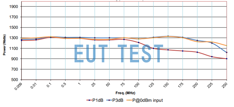
Learn how to select an RF power amplifier for EMC testing from a graph of the relationship between the 1dB compression point and the 3dB compression point of an amplifier.
Above is how to choose RF power amplifier for EMC test related knowledge points, if you still have any questions you can contact us, we will provide you with more technical information about EMC power amplifier when we provide the goods.