
Status quo facing EMI rectification?
When diagnosing electromagnetic interference (EMI) problems, electronic design engineers are faced with the difficult problem of identifying the sources of interference emissions and developing solutions to eliminate them. Often, the only information available from an EMC test lab is a spectral curve that indicates which frequencies are heavily emitting or exceeding template limits. Finding and fixing problems through repetitive testing in an EMC conformance lab is not only costly, but often results in significant delays in product launch. Learn how to use oscilloscopes and near-field probes for EMI diagnostics below.
EMI rectifies the necessary equipment:
digital oscilloscope
Digital oscilloscopes such as the RTO, which EUTTEST represents and sells, are important tools for analyzing EMI problems in electronic design. High input sensitivity, high dynamic range and powerful FFT processing are key to capturing and analyzing interference radiation.FFT is a software tool that converts the time domain into the frequency domain, allowing simultaneous observation of both time and frequency domain data during testing.
More optional oscilloscope products:oscillograph
Overlapping FFT processing using color-coded display of spectral components
In RTO digital oscilloscopes, the overlapping FFT processing first automatically splits the captured time domain signal into overlapping segments. In step 2, the RTO digital oscilloscope calculates the FFT of each segment, and then displays the FFTs of these segments overlaid so that intermittent signals, such as pulse-like interference, can be observed. Intermittent signals can be observed by color coding the resulting spectral profile according to the frequency at which the signal occurs.
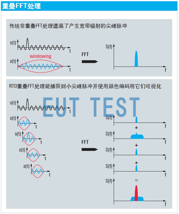
Overlapping FFT processing for color-coded display of spectral components using an oscilloscope
Time-frequency domain correlation analysis using Gated FFTs
A selective FFT function is used to enable spectral analysis of signals in a user-defined time region. Bursts of excessive spectral radiation may be associated with specific time periods in the signal. Typical applications include interference radiation associated with fast switching edges in a switching power supply, or with the transmission of data on a bus interface. After identifying the problem, by observing the level change of the spectral radiation, the design engineer can easily check the effectiveness of different solutions such as using isolation capacitors or reducing the rise/fall time.
Capturing bursts using frequency templates
Intermittent or bursts of radiation are the most difficult to diagnose. They are not easy to capture and are difficult to analyze, and the R&S®RTO template tool makes it easy to capture these events. Once the frequency template test is violated, capture stops automatically and the user can adjust the FFT settings (e.g., resolution bandwidth or pass-through function) and use additional tools (e.g., cursors) for more in-depth analysis.
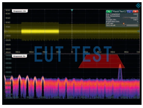
Capturing Bursts with Oscilloscope Frequency Stencils
spectrograph
EUTTEST agent sales of the spectrometer does not show the time domain only shows the frequency domain, but does not need to convert the FFT time, for some high-speed or transient emission signals using the spectrometer will get more direct test results. And the spectrometer can also complete some EMC standards for EMI testing.
Detailed product list:spectrum analyzer
Near field probe
The near-field probes sold by EUTTEST agent are divided into electric field near-field probes and magnetic field near-field probes. EMI interference signals can be measured deep into the PCB surface or near the connector and displayed in the oscilloscope and spectrometer mentioned above.
Detailed product list:Near field probe