Impedance of the power delivery system
Power Delivery Systems are also called Power Delivery Systems or Power Supply Systems, or PDS for short.
The impedance of a PDS is defined as the fact that the power starts from the power module and generally passes through the circuit board, the package and the interconnections inside the chip and finally to the transistors. This is a layered power network, which we generally call Power delivery system (PDS). The core content of power integrity analysis is how to design the power ground network to minimize the noise generated. Therefore, the impedance of PDS is defined as the impedance of the whole power delivery system as viewed from the chip end:
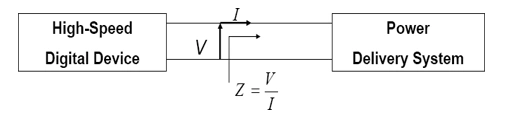
Impedance Definition Schematic for PDS Power Delivery System
The design goal of PDS is to reduce the impedance of the entire network and thus reduce the noise of the power ground network. While the target impedance Ztarget examines the passive power ground network design, the formula for Ztarget is shown below:
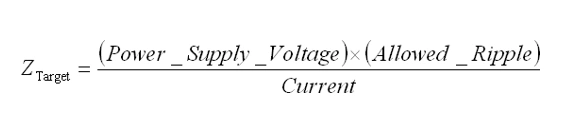
Calculation formula for target impedance Ztarget
For example, for a 3.3-volt power plane, if the allowable voltage fluctuation is 5% and the current through it is 2 amps, then we can find the target impedance to be 82.5 milliohms.
Ztarget = (3.3*5%)/2=82.5mΩ
That is, the impedance of the entire PDS system is less than 82.5 milliohms, and the power integrity of this system is not a problem, i.e., the fluctuation is less than 5%. Of course the actual math is not so simple, because the current value is not constant, but frequency dependent, so the target impedance is also a frequency dependent value.
- Created Date: 2025-03-13 15:30:50 ;
- Last modified on 2025-07-18 18:05:49 ;