
The coupling modes of electromagnetic nuisance are usually categorized into two main groups: i.e., propagation by conducted nuisance and propagation by radiated nuisance.
- Electromagnetic nuisance propagated through a conductor is called conducted nuisance;
- Electromagnetic nuisance propagated through space is called radiated nuisance.
Below you will learn the coupling methods of conducted and radiated nuisance, and the two types of interference suppression illegal, measurement, rectification process.
Conducting harassment:
Conducted nuisance, sometimes called conducted interference, can be broken down into the following ways of coupling:
common impedance coupling (physics)
The common impedance coupling of the conducted nuisance is generated by the coupling of two circuits via a common impedance, and the amount of interference is the current I or the varying current di/dt.
tolerant coupling
The capacitive coupling of conducted nuisance arises from the presence of a distributed capacitance between the source of the interference and the interference symmetry, and the quantity of the interference is the varying electric field, i.e., the varying voltage du/dt.
inductive coupling
The inductive coupling of the conducted nuisance arises from the presence of mutual inductance between the source of the interference and the interference symmetry, and the quantity of the interference is the varying magnetic field, i.e., the varying current di/dt.
How to suppress conduction interference?
After understanding the above types of conducted interference coupling, we need to use different interference suppression illegal for each type of coupling.
Common impedance coupling interference suppression method
- Make two current circuits or systems independent of each other. The signals are independent of each other and the connection of the circuits is avoided in order to avoid the formation of circuitous coupling.
- Limit the coupling impedance, so that the lower the coupling impedance, when the coupling impedance tends to zero, known as circuit decoupling. In order to make the coupling impedance is small, must make the wire resistance and wire inductance are as small as possible.
- Circuit decoupling: i.e., the different current circuits are electrically connected only at a single point, where no circuit interference current can flow, thus achieving the purpose of circuit decoupling between current circuits.
- Isolation: Isolation techniques are often used for related systems with significant level differences (e.g., between signal transmission equipment and high-power electrical equipment).
Capacitive coupling interference suppression method
- The following measures can be taken to suppress capacitive interference:
- The electrical parameters of the interference source system shall be such that the magnitude and rate of change of voltage shall be as small as possible;
- The disturbed system should be designed to be as low resistance as possible;
- (b) The coupling parts of the two systems should be arranged so that the coupling capacitance is as small as possible. Wire and cable systems, for example, should be spaced as widely as possible, with short wires, to avoid parallel routing;
- Electrical shielding can be applied to the interference object of the interference source. The purpose of shielding is to cut off the power line path between the conductor surface of the interference source and the conductor surface of the interference object so that the coupling capacitance becomes minimum;
Inductive coupling interference suppression method
- The electrical parameters of the interference source system should be such that the magnitude and rate of current change is as small as possible;
- The disturbed system should have high impedance;
- Reduce the mutual inductance of the two systems by keeping the conductors as short as possible, spacing them as widely as possible, avoiding parallel routing, and reducing the area enclosed by the current loop when using a two-wire construction;
- Magnetic shielding is provided for interference sources or objects to suppress the interference magnetic field.
- The use of balancing measures, so that the interference field as well as the coupling of most of the interfering signals cancel each other out. If the interfering wire ring is placed in the interference field in a way that cuts the magnetic lines of force at a minimum (ring direction parallel to the magnetic lines of force), the coupled interference signal is minimal; in addition, such as the interference source wire balanced stranded, the magnetic field generated by the interfering currents can be canceled out each other.
Radiation Harassment:
Radiation harassment is sometimes called radiation interference, radiation interference through the space transmission is essentially the electromagnetic energy of the interference source in the form of a field to the surrounding space propagation, from the distance of the interference is divided into "near-field radiation interference" and "far-field radiation interference".
How can I tell if it's near-field radiated interference versus far-field radiated interference?
The near field is also known as the induced field and the far field is also known as the radiated field.
The criterion for determining the near-field far-field is determined by the distance r of the EUT from the emitting field source.
- r>λ/2π is then the far field
- r<λ/2π is then the near field
We often use wave impedance to describe the relationship between electric and magnetic fields, and the wave impedance Zo is defined as
- Zo=E/H
In the far-field region, the electric and magnetic fields are perpendicular to each other and to the direction of propagation, which is called a plane wave, and the ratio of the electric field to the magnetic field is a fixed value of Zo=120∏=377 ohms. The following figure shows the relationship between the wave impedance and the distance from the field source.
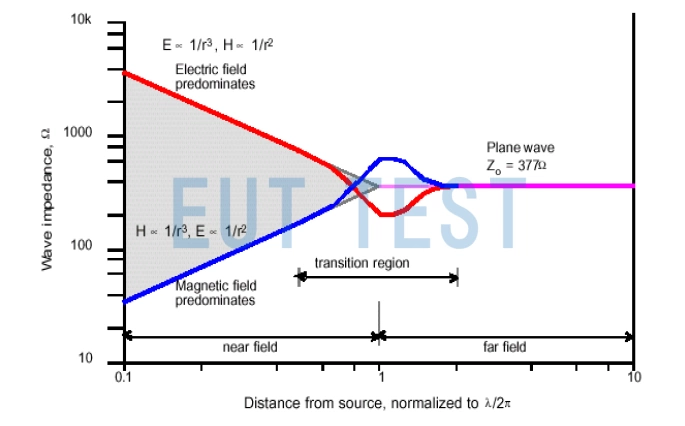
Electromagnetic nuisance coupling mode-wave impedance versus distance from field source
How are near-field and far-field interference tested?
We can use some EMC test rectification equipment to complete the near-field and far-field radiated interference components.
When measuring the near-field interference of an EUT, we generally use the "Near field probe" to measure the surface of the EUT, because the near-field probe is very small, ideal for insertion inside a narrow PCB or chassis, and it can locate specific sources of interference. For example a section of alignment or discrete components.
When we measure the far-field interference of an EUT, we need to measure the interference at a long distance (e.g., at the 3-meter method).Anechoic chamber(or 10-meter FEM darkroom) useEMI receiving antennarespond in singingEMI Receiverto measure the radiated interference level, and then still choose the near-field probe to measure the PCB of the EUT again, when in the far-field measurement there is a 200MHz frequency point measured very high 100dBμV/m (dB is the decibel unit.If the PCB is not in a position to transmit the radiation (dBμV/m is used to express the strength of the electric field), you only need to measure the PCB again with a near-field probe to find out where the source of the 200 MHz emission is located.
So, rectifying radiated nuisance is as simple as that. When the specific location of the emission source is found, we can use the following different measures to reduce radiated emission nuisance to complete the debugging and rectification of near-field interference or far-field interference.
Measures to reduce radiation interference
- The main measures to minimize radiation interference are:
- Radiation shielding: Inserting a piece of metal shielding between the source of interference and the object of interference to block the propagation of the interference.
- Polarization isolation: The interference source and the interference object take polarization isolation measures in the layout. That is, when one is vertically polarized, the other is horizontally polarized to reduce the coupling between them.
- Distance isolation: the distance between the interference source and the object being interfered with, this is due to the fact that in the near-field area, the field strength is proportional to the distance open square or cube, when the distance increases, the field attenuation is very fast.
- Absorption coating method: The object being interfered with can sometimes be coated with a layer of material that absorbs electromagnetic waves in order to minimize the interference.