
Introduction:
This article is the second part of EUTTEST's EMC modification of commonly used devices, mainly introduces the characteristics of the inductor, especially at high frequencies and the equivalent circuit, and finally explains the role of common mode inductors and differential mode inductors in detail.
Characterization of inductors:
Inductors are a common electronic component, inductors are inexpensive to produce, we can use it to design circuits, but also can be used to rectify EMC problems.
Inductance in application is mainly characterized by the fact that high-frequency signals cannot conduct while low-frequency signals can pass through, which is the opposite of the characteristics of capacitance. Moreover, when the frequency f is larger, we can see that the inductive reactance obtained is larger, which means that the high-frequency current is less likely to pass through.
High-frequency characteristics of inductors:
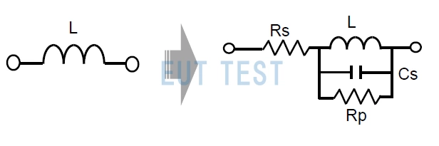
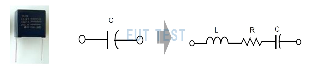
At high frequencies the inductance is affected by the effect of the transmission line, and in this case the inductor is not only inductive, but also has capacitive and resistive effects.
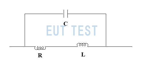
High Frequency Characteristics of Inductors
As can be seen from the figure above, the inductor is no longer a single component in the high frequency circuit, but has become a L and R in series, and then connected in parallel with a capacitor equivalent circuit. Due to the high frequency inductor capacitance C within the impedance value will become lower, this time the inductor equivalent circuit is easy to form a parallel resonance circuit, resonance circuit resonance frequency will affect the circuit's maximum operating frequency.
Because the physical structure of the inductor has a capacitive effect, which makes the original to inhibit the high-frequency noise but because of the capacitive effect and direct conduction, which can not be achieved to filter out the effect of high-frequency microwave. Therefore, we also use magnetic beads or ferrite to replace the inductor in the actual rectification of EMC. See the end of the third part of the article - ferrite and magnetic beads in the relevant content.
Common mode inductors:
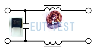
Common mode inductor equivalent circuit diagram
The equivalent circuit diagrams of common mode inductors commonly found on the market are shown in the figure above, next we will learn about the fabrication schematic of common mode inductors:
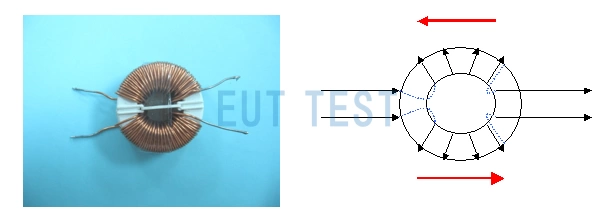
Common Mode Inductor Fabrication Schematic
From the common mode inductor design schematic shown above, the common mode inductor is composed of two cables are wrapped around the same bead, they do not intersect, and their current direction is opposite, we can use the right hand Ampere's rule to determine the direction of the magnetic field according to the direction of the current, at this time the two cables have a common-mode current exists, the two cables with the current is the opposite direction and the size of the same, which makes the common mode inductor around the There are two different polarization of the magnetic field, they are perpendicular to the intersection, cancel each other. This also solves the problem of common mode interference in EMC.
Common mode inductors can solve common mode interference problems
When we have applied the common mode inductor, we have listed in the graph below a comparison of the conducted test results before and after the addition of the common mode inductor. As you can see from the graph, the conduction emission curve has been successfully reduced below the limit line with the addition of the EMC rectification components.
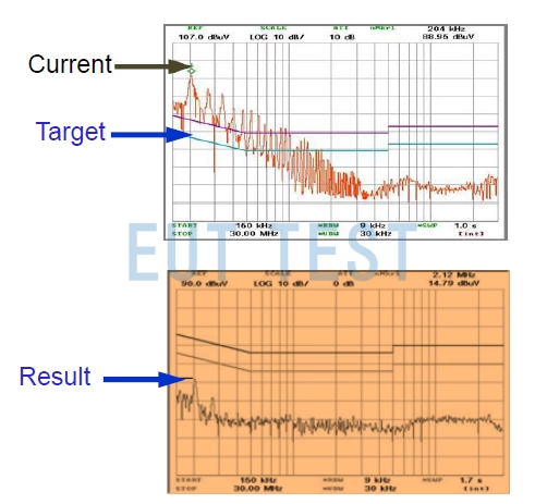
Comparison of conduction test results before and after adding a common mode inductor
Common mode inductors are not effective for differential mode noise:
According to the above analysis, when the common mode noise through the common mode inductor is replaced by the differential mode noise, the magnetic field generated by them will be equal in size and direction and be strengthened, so the common mode inductor is ineffective for the differential mode noise.
Differential mode inductors:
Differential Mode Inductor Equivalent Circuit Diagram
Now we load the differential mode inductor into the circuit.
Load the differential mode inductor into the circuit
The following figure shows a comparison of the conduction test results before and after the addition of the differential mode inductor, and it can be seen that the differential mode noise has been suppressed below the limit line.
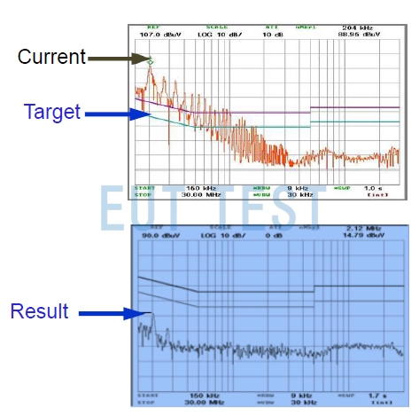
Comparison of conduction test results before and after the addition of differential mode inductors
How to design a filter?
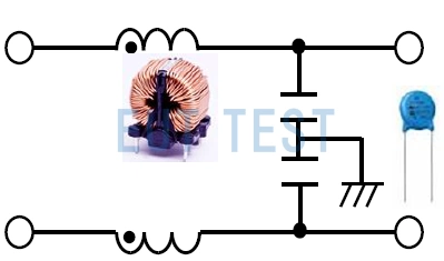
Once we have found the right common mode inductor and differential mode inductor, it is straightforward to combine the two inductors into a single filter component. Of course, you can also add the X-capacitor and Y-capacitor together into the filter design, after all, they are both there to rectify the conducted emission noise in the EMC problem.
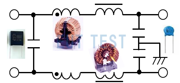
The combination of a differential mode inductor and a common mode inductor is called a filter
How to choose between common mode inductors and differential mode inductors?
Before choosing an inductor as an EMC rectification component, we need to test the total interference output of the product, which will contain both differential mode and common mode interference, and then we need to clarify the EMC problem from thecommon-mode interferenceneverthelessdifferential mode interferenceIf we use the EUTTEST recommendedConducted common mode differential mode splitterYou will quickly get a comparison of common mode and differential mode separated signals, and then you can solve the EMC problem according to the principle of using common mode inductors for common mode disturbances and differential mode inductors for differential mode disturbances.
Conclusion:
There is also a wide range of components that can be used for EMC rectification, you can click on the following links for more information.
- EMC rectification commonly used devices - Part I - capacitors
- EMC rectification commonly used devices - Part II - inductors (this article)
- EMC rectification commonly used devices - Part III - Ferrite magnetic rings and beads
- EMC rectification commonly used devices - Part IV - electromagnetic shielding film patch
- EMC rectification commonly used devices - Part V - copper and aluminum foils
- EMC rectification commonly used devices - Part VI - copper braid and grounding wire
- EMC rectification commonly used devices - Part VI - conductive paint and metal sheet