
Introduction:
This article is the first part of EUTTEST's EMC rectification of commonly used devices, mainly introduces the types of capacitors, characteristics, operating frequency, as well as common X-capacitor and Y-capacitor characteristics of the introduction.
Types of capacitors and their operating frequencies:
The most common capacitors we use in hardware development and their operating frequencies are shown in the table below:
“Reminder: swipe tables left and right”Characterization of capacitors:
Capacitor is a common electronic component that we can use to design circuits and also to rectify EMC problems. In addition it has the following two characteristics that are worth considering and choosing to use.
Low cost:
Because capacitors are so common, they are inexpensive and very inexpensive to purchase.
Passes high frequencies and blocks low frequencies:
The main characteristic of a capacitor is that high frequency current signals can easily pass through, but low frequency signals will be difficult to pass or even unable to conduct because of the presence of capacitive reactance.
The capacitive reactance of the capacitor is calculated as follows:
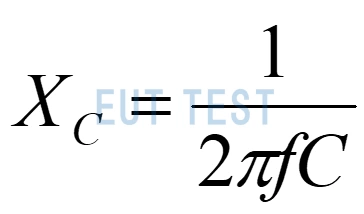
Capacitive Reactance of Capacitor Calculation Formula
Xc is the capacitive reactance of the capacitor
F is the operating frequency
C is the capacitance
Xc is inversely proportional to f. When the frequency f is very small, the capacitive reactance Xc will be very large, resulting in the signal not being able to pass through and blocking the low frequency;
Xc is inversely proportional to f. When the frequency f is large, the capacitive reactance Xc will be very small, resulting in the signal being able to pass through and pass high frequencies.
Several different capacitor connections:
Since capacitors are short-circuit conductive for high-frequency signals, we can use this property of capacitors to conduct high-frequency currents from the signal to ground without affecting the clock frequency of the signal line.
The role of the capacitor is to conduct the energy of high frequency noise to the grounded metal, so it does not attenuate the noise energy by itself, and the size of the grounding of the capacitor connection becomes important.
However, we should also be aware of several different ways of connecting capacitors.
- Bandpass capacitance: can filter out high frequency noise on the signal line, capacitance value is generally 1000pF-10pF, capacitance value selection must pay attention to whether it will affect the signal quality. For example, the X capacitance and Y capacitance mentioned later.
- Decoupling capacitor: can filter out the noise of the power supply, the capacitance value is generally 0.1uF.
- Rectifier capacitors: can provide the role of voltage regulation, capacitance value is generally 1uF-10uF, usually in the rectifier bridge and other large current consumption of welding.
X-capacitance and Y-capacitance:
X and Y capacitors are commonly used in power supply filtering, such as filters in dark rooms or shielded rooms, and AC and DC power supply filters designed by engineers themselves. Since most of the power supplies have high voltage and high current, the industry usually requires X and Y capacitors to comply with IEC 60384, 2nd Edition, Table II.
X capacitance:
When the X-capacitor has a high capacitance, the IEC 60065 safety test standard requires that the discharge capacity between the two pins of the capacitor should not exceed the IEC 60065 (0.7mA peak at about 34V) within 1 to 2 seconds after the plug is removed from the power supply. Generally, X-capacitors with a capacitance not exceeding 1uF can meet the above requirements. Common X-capacitors are shown in the figure below, and they vary in size according to their capacity.
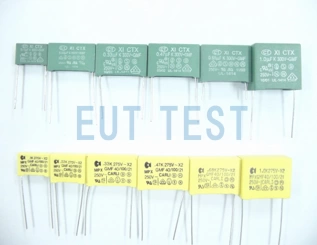
Common X-capacitors
How to use X-capacitor?
The X capacitor can be used by connecting it directly across the L and N wires.
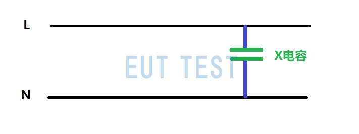
X capacitance across the L and N lines
X-capacitors are commonly used indifferential mode interferenceThe EMC rectification.
Y capacitor:
When the X-capacitance is high, the IEC 60065 safety test standard requires that the leakage current between the two pins of the capacitor should not exceed the IEC 60065 (0.7mA peak) when the plug is removed from the power supply. Generally, Y-capacitors with a capacitance of up to 4700uF can meet the above requirements. Common Y-capacitors are shown below, and they vary in size according to capacity.
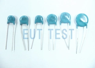
Common Y capacitors
How to use Y-capacitor?
Use the Y capacitor by connecting it directly across L-GND or N-GND.
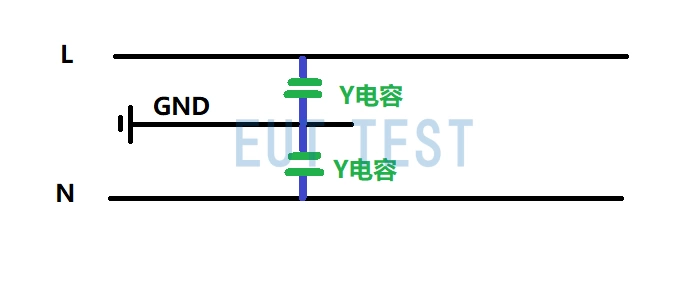
Y capacitor across L-GND or N-GND
As shown in the figure above, the high frequency EMC signal will flow to the GND ground point through the Y capacitor.The Y capacitor is commonly used in thecommon-mode interferenceThe EMC rectification.
How do I determine whether to choose a Y or X capacitor?
Once the above basics are understood, we need to select the correct capacitor according to the EMC rectification and debugging needs. From the previous section, we know that the X capacitor is connected differently from the Y capacitor, so we need to first confirm that the EMC problem comes from common mode interference or differential mode interference, if we use the EUTTEST recommendedConducted common mode differential mode splitterYou will quickly get a comparison of common mode and differential mode separated signals, and then you can solve the EMC problem according to the principle of using Y capacitor for common mode interference and X capacitor for differential mode interference.
Conclusion:
There is also a wide range of components that can be used for EMC rectification, you can click on the following links for more information.
- EMC rectification commonly used devices - Part I - capacitors (this article)
- EMC rectification commonly used devices - Part II - Inductors
- EMC rectification commonly used devices - Part III - Ferrite magnetic rings and beads
- EMC rectification commonly used devices - Part IV - electromagnetic shielding film patch
- EMC rectification commonly used devices - Part V - copper and aluminum foils
- EMC rectification commonly used devices - Part VI - copper braid and grounding wire
- EMC rectification commonly used devices - Part VI - conductive paint and metal sheet