
In the EMC industry, many customers ask EUTTEST whether the electric and magnetic fields obtained from their measurements using EMI antennas or probes can be converted to each other? The following is an analysis of the electric and magnetic field conversion formulae from both near-field and far-field test methods.
If you have no experience in EMC testing, it is recommended that you learn it first:About the concept of EMC electromagnetic compatibility and EMC test system introduction
During far-field testing:
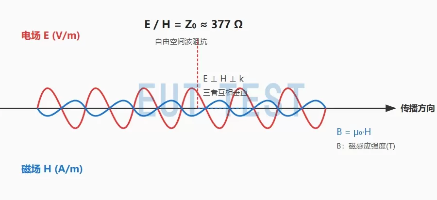
Plot of electric and magnetic field propagation at far field
- The electric field E, the magnetic field H, and the direction of propagation k are perpendicular to each other (the right-hand rule).
- E and H are in the same phase and reach maximum/minimum at the same time.
- E / H = 377Ω (free space wave impedance)
- B = μ₀ × H (magnetic induction is proportional to magnetic field strength)
Far-field free space calculation formula:
- Free-space wave impedance: Z0 = √(μ0/ε0) ≈ 377 Ω;
- Vacuum permeability μ0 = 4π × 10^(-7) ≈ 1.257 × 10^(-6) H/m
- E: electric field strength in V/m;
- H: Magnetic field strength in A/m;
- B: Magnetic induction in T (Tesla)
Note that when the units are changed and the units are no longer the standard A/m and T, the units have to be converted before calculations can be made.
- H (A/m) ≈ 795.8 x B (mT)
- 1 mT ≈ 795.8 A/m
- 1 T = 1000 mT
Common unit conversions
- 1 T = 10^(4) G
- 1 G = 10^(-4) T
- E(dBμV/m) = 20-log10( E(V/m) × 10^(6) )
Calculation example:
It is known that E = 10 V/mH = 10 / 377 ≈ 0.0265 A/m; B ≈ 1.257 × 10^(-6) × 0.0265 ≈ 3.33 × 10^(-8) T
During near-field testing:
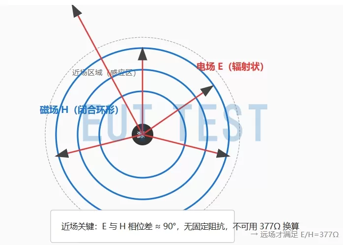
Plot of electric field versus magnetic field at near field
✔ Near field (induced field): distance from antenna/coil < λ/2π area
✔ E and H are in different phases and do not reach maximum/minimum at the same time
✔ E & H No Fixed 377Ω Wave Impedance
✔ E and H are not uniformly distributed and are not directly interchangeable
✔ Magnetic fields are predominantly circular and electric fields are predominantly radial
There are no formulas available because they are not convertible for near-field testing.
caveat
In summary, we can summarize that the electric and magnetic field conversion formulas conform to the following points:
The above E↔H conversion formula is only applicable to far-field plane waves (EMC radiated nuisance, antenna far-field).
Near field (coil,industrial frequency magnetic field,Near field probe,shielded roomNearby area,current probe(377Ω is not available for conversion.
Industrial 50/60Hz magnetic fields are generally used directly as B (μT, nT) or H (A/m) and are not directly converted to electric fields.
EMC standards: far-field radiation: commonly used E (V/m, dBμV/m); magnetic field: commonly used H (A/m) or B (μT, nT)
More EMC formulas are detailed:free download db conversion formula for emc industry
 EMC Test Program Introduction