
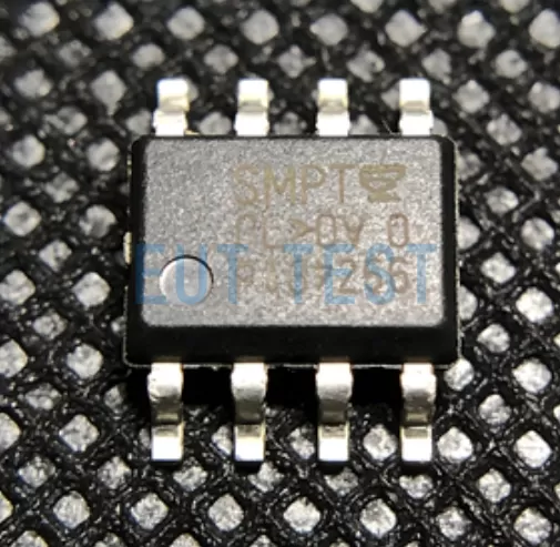
Introduction:
Due to their high reliability and long service life, optocouplers are used wherever safe electrical isolation of two circuits is required, e.g. in switched-mode power supplies (SMPS). When optocouplers are used to protect a system from electrical damage, they must comply with the relevant VDE standards and/or international standards (e.g. IEC standards), such as DIN EN 60747-5-2 (VDE 0884) as well as DIN EN 60747-5-5, DIN EN IEC 60747-17 (VDE 0884-17) for safe electrical isolation of the What standards do I need to be concerned with for optocouplers or digital isolators? At the end we will list some of the existing standard numbers for your reference.
The current trend is to incorporate international standards (e.g. IEC standards) into the regulatory system of the German Institute of Electrical Engineers (IEEE). On the other hand, the goal is to transform a German national IEEE standard (e.g. one that has been proven to enhance safety) into an internationally recognized IEC standard. For example, a new German standard, German Industrial Standard/European Standard 60747-5-5 (corresponding to IEEE Standard 0884), has just been introduced and is also under consideration in various international standardization committees.
Early German VDE standards were divided into three main categories (most of which are no longer valid in 2026):
- Basic VDE standards, e.g. VDE 0110, which define the requirements for electrical clearances and creepage distances in general.
- VDE standards for regulated components, e.g. VDE 0883 for optocouplers, which recently expired
- VDE standards regulating systems and equipment, e.g. VDE 0805/0806 for office machines and electronic data-processing systems
Optocouplers for computer switch-mode power supplies (SMPS) must fulfill the requirements of VDE 0883 as well as VDE 0805/0806.
The thickness of the solid insulation layer between conductive parts, the insulation test voltage as well as the electrical clearance and creepage distances are of vital importance in applications where reliable electrical insulation is required. Depending on the sensitivity of the application, different values are specified in the VDE standards.
For example, electrical control cabinets may be opened and operated rarely and only by specialized personnel. However, it is not uncommon for a cup of coffee to be accidentally spilled on the keyboard of an electric typewriter. The requirements to be met in these two situations are therefore quite different.
Recent findings in the field of high-voltage technology have called into question the two parameters of solid insulation thickness and insulation test voltage. It is true that the dielectric strength increases with the thickness of the insulation, but this conclusion only applies if the insulation is of uniform texture, free of impurities and air bubbles. A good quality thin insulating layer may outperform a thick insulating layer containing impurities or air bubbles. The current trend is clearly toward reducing the thickness of the insulating layer (about 0.3 mm to 0.5 mm) in order to achieve more economical manufacturing as well as technologically advanced optocoupler functionality.
To test for breakdown strength, the isolation test voltage is typically sustained for 60 seconds during the qualification test; and for up to 1 second (depending on the specific VDE standard) when the full 100% test is required by Method B described below. However, the test cannot determine whether partial discharges have occurred in the insulation during the test. This requires extremely sensitive measuring equipment, which has only recently been introduced to the market.
Research in the field of high-voltage technology has shown that single partial discharges are likely to be unextinguishable at low voltages and that persistent partial discharges may deteriorate and cause damage to insulating materials. Therefore, partial discharges may occur even under normal operating conditions when an operating voltage is applied. After a certain operating time, high voltage breakdown is likely to occur.
The new standard DIN EN 60747-5-5 (VDE 0884) for optocouplers for safe electrical isolation addresses two previously mentioned shortcomings. Today, the appropriate dielectric strength is determined by the presence of partial discharges at a specific test voltage. Partial discharges occur when impurities or air bubbles are present in the insulating material or when the solid insulation layer is too thin.
The conventional withstand breakdown test (isolation test voltage) may cause initial damage to the optocoupler which cannot be detected. the DIN EN 60747-5-5 standard has replaced this test with a partial discharge test using theHT9464maybeHT-9464MPartial discharge voltages of up to 10KV rms can be applied on both sides of the optocoupler or digital isolator, and both devices can also detect any partial discharge phenomena. If you use EUTTEST's9464 Test SystemIf you find no partial discharge after the test, it means that the product has a reliable isolation capability without causing any undesirable initial damage to the insulating material.
Partial Discharge Measurement Methods by Standard
Both measurement methods have proven to be reliable and suitable for optocouplers or digital isolators according to DIN EN 60747-5-2 (VDE 0884) as well as the descriptions in DIN EN 60747-5-5, DIN EN IEC 60747-17 (VDE 0884-17).
- Measurement method A: Destructive testing for optocoupler certification and sample testing in production
- Measurement method B: non-destructive testing of each element (100% full inspection)
Figures 1 and 2 below show two typical voltage time profiles (AC voltage peak-to-peak) when testing optocoupler/digital isolator chips according to DIN EN 60747-5-2 (VDE 0884)/DIN EN 60747-5-5 standard, with test status to be determined.
Optocoupler qualification destructive testing and sampling in production.

Figure 1: DIN EN 60747-5-5 (VDE 0884-11/17) Method A
Method A mainly describes the setting of PD test time of 10 seconds on HT9464 or HT-9464M instrument, of course, it can also be set on the software, in addition, it is also necessary to set the isolation voltage detection time of 60 seconds, these two can be completed in our equipment in turn, 9464 test system with the sorter we provide can realize the automated testing needs, for the million level production. Such a test configuration can greatly reduce the test time.
Especially the method B shown in the figure below, which is required to test all 100% of optocoupler chip/digital isolator chip products, that is to say, each product has to be tested once, so the 9464 test system is still the optimal choice.

Figure 1: DIN EN 60747-5-5 (VDE 0884-11/17) Method B
In addition to the PD partial discharge test mentioned above, the DIN EN 60747-5-2 (VDE 0884)/ DIN EN 60747-5-5/ DIN EN IEC 60747-17 (VDE 0884-17) standard imposes further requirements for improving the reliability of optocouplers. For example, reliability limit data such as limit current, temperature and/or power consumption must be provided for each approved and qualified component. The limit values are usually higher than the maximum ratings. They are used to indicate whether additional components are required in the circuit to ensure safe electrical isolation in the event of a peripheral circuit failure.
In qualification testing (destructive testing), the optocoupler is subjected to a number of tests in harsh environments such as humidity cycling and temperature shock. The optocoupler is then stressed to its limit value for 72 hours. Finally, it is subjected to partial discharge testing. Currently, no partial discharge (PD) is defined as a leakage charge value of less than 5 pC when tested with the 9464 system.
In summary, optocoupler or digital isolator chip products used in safety electrical isolation applications are subject to theDefect-free testing of partial dischargesto improve reliability and provide valid reference information on the long-term stability of insulation materials. The partial discharge measurement technique may be applicable to transformers, capacitors and other components. Since December 1988, the VDE 0883 standard is no longer valid. However, as of the end of 1991, certification according to VDE 0883 was still recognized on the market.
Since 1992, optocouplers must hold DIN EN 60747-5-2 (VDE 0884)/DIN EN 60747-5-5 certification. Only DIN EN 60747-5-2 (VDE 0884)/DIN EN 60747-5-5 certified optocouplers may be used for new designs of printed circuit boards or systems that utilize optocouplers and that are subject to electrically safe isolation requirements.
List of standards related to couplers:
It's 2026, if you are an optocoupler or digital isolator manufacturer, OEM factories should start to pay attention to the following list of standards and alternative relationships, the following list is updated in 2026 04:
“Reminder: swipe tables left and right”IEC 60747-5-2:1997+AMD1:2002 CSV
IEC 60747-5-2:1997+A1:2002 specifies the basic ratings and characteristics of the following classes or subclasses of optoelectronic devices, which are not applicable to the field of fiber optic systems or subsystems:
- Semiconductor photoelectric emitters, including: light emitting diodes (LEDs); infrared emitting diodes (IREDs); laser diodes.
- Semiconductor photodetectors, including: photodiodes; phototransistors.
- Semiconductor photosensitive devices.
- Semiconductor devices that utilize optical radiation for internal operation, including: optocouplers, optical couplers.
This consolidated version consists of the first edition (1997) and its amendment 1 (2002).
Replaced by the following criteria:
IEC 60747-5-7:2016.
IEC 60747-5-6:2016.
IEC 60747-5-5: 2007
IEC 60747-5-4: 2006
IEC 60747-5-4: 2006
Covers semiconductor laser terminology, basic ratings and characteristics, and measurement methods.
IEC 60747-5-5: 2007
This part of IEC 60747 provides terminology, basic classes, characteristics, safety tests and measurement methods for optocouplers (or photocouplers). Note: The term “optocoupler” may also be used in place of “optocoupler”. This standard replaces the terms optocoupler (or optocouplers) described in IEC 60747-5-1, IEC 60747-5-2 and IEC 60747-5-3 and their revisions, which will be considered obsolete on the date of publication of this standard. standard will be considered obsolete as of the effective date of publication of this standard. NOTE: Optocouplers certified to the previous version of the standard for optocouplers (i.e. IEC 60747-5-1/2/3) shall be considered to comply with the requirements and provisions of IEC 60747-5-5.
Latest version: IEC 60747-5-5:2020
IEC 60747-5-6:2016.
IEC 60747-5-6:2016 specifies the terminology, basic ratings and characteristics, measurement methods and quality assessment of light-emitting diodes (LEDs) for general industrial applications (e.g. signals, controllers, sensors, etc.). LEDs for lighting applications are outside the scope of this part of IEC 60747.The types of LEDs are categorized into the following five main groups:
a) LED encapsulation.;
IEC 60747-5-7:2016.
IEC 60747-5-7:2016 specifies the terminology, basic ratings and characteristics, and methods of measurement of photodiodes (hereinafter referred to as “PDs”) and phototransistors (hereinafter referred to as “PTs”). This standard replaces the photodiode and phototransistor clauses described in IEC 60747-5-1, IEC 60747-5-2 and IEC 60747-5-3 and their amendments. As a result of the reorganization, IEC 60747-5-1, IEC 60747-5-2 and IEC 60747-5-3 and amendments thereto are superseded by the publications IEC 60747-5-4, IEC 60747-5-5, IEC 60747-5-6 and IEC 60747-5-7.
IEC 60747-17:2020
IEC 60747-17:2020 specifies the terminology, basic ratings, characteristics, safety tests and measurement methods for magnetic and capacitive couplers.
It defines the principles and requirements for insulation and isolation characteristics of magnetic and capacitive couplers in terms of basic and reinforced insulation.
This first edition cancels and replaces IEC PAS 60747-17:2011.This edition is a technical revision.
This edition contains the following important technical changes to IEC PAS 60747-17:2011:
a) A life-cycle safety factor has been introduced to enhance life-time considerations to comply with the widely recognized aging mechanisms of silica (TDDB) and thin-film polymer barrier layers; and;
(b) Significantly improved the “end-of-life testing” paragraph and statistical life considerations by adding a detailed description of the process, safety margins, methodology for generating data points and corresponding life-cycle interpolations, as well as specifying the number of samples required.;
(c) Introduced the concept of certification by similarity, including Appendix A, which provides guidance on eligibility considerations and the required certification process.;
d) Alternative pulse shapes allow for surge pulse testing to avoid problems with surge tester availability.;
e) A number of improvements in the standard: definitions (e.g. coupler types have been improved), introduction of surge impulse VIMP ratings, use of glass transition temperatures, pre-processing methods to improve usability and better compatibility with existing coupler and mold formulations, etc.
The January 2021 correction is included in this copy.
(IEC 60747-17:2020 + COR1:2021); German version EN IEC 60747-17:2020 + AC:
This International Standard provides terminology, basic ratings, characteristics, safety tests and measurement methods for magnetic and capacitive couplers. It specifies the principles of insulation and insulation characteristics of magnetic and capacitive couplers
and the associated requirements for basic isolation and reinforced insulation.
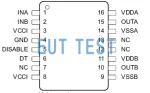 DIN V VDE V 0884-11 (VDE V 0884-11): 2017-01 Certification Test Program Overview
 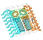 Purpose and significance of Qpd partial discharge test
 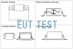 Certified Test Programs for Digital Isolators and Optocouplers