
CS101 Introduction:
CS101 is one of the test programs of the Military EMC Standard, which is designed to verify that military electronic products will function properly when power line conducted interference as described below is applied. Suitable for CS101 testing in the 30 Hz - 150 kHz frequency range, including AC powered equipment and subsystems where AC current ≤ 30 amps per phase (100A for GJB15B-2013); and DC input power lines (excluding return lines).
(New MIL-STD-461G requirement) For currents in excess of 30 amperes per phase, this requirement also applies if the system operates at 150 kHz or less and has an operating sensitivity of 1 μV or greater (e.g., 0.5 μV). If the equipment under test (EUT) is DC operated, this requirement applies to the frequency range of 30 Hz to 150 kHz. If the EUT is AC operated, this requirement applies starting at the second harmonic of the EUT supply frequency and extending to 150 kHz.
CS101 Limit
When the EUT is subjected to a test signal at the voltage level shown in Figure CS101-1, there shall be no malfunction, degradation of performance, or deviation from the specified indications beyond the tolerances indicated in the individual device or subsystem specifications. This requirement is also considered to be met when the power supply is adjusted to consume the power level shown in Figure CS101-2 at a 0.5 ohm load and the EUT is not affected.
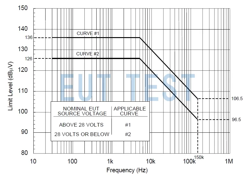
CS101-1 Limit Line-Voltage
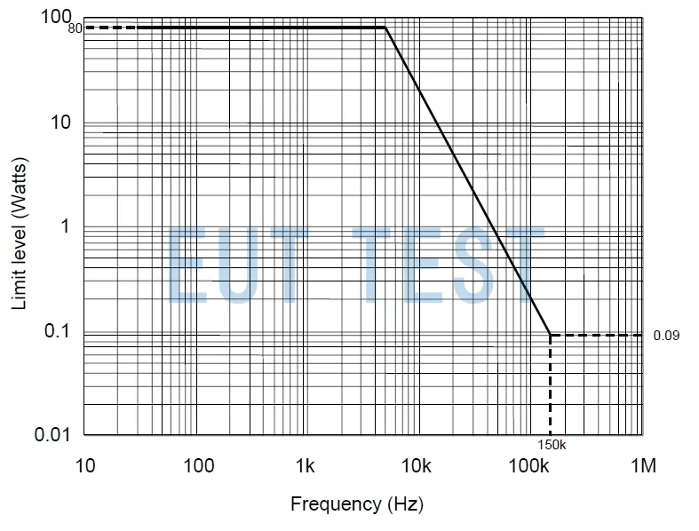
CS101-2 Limit Line-Power
CS101 Test equipment and systems
The CS101 is primarily used to verify the immunity tolerance of the EUT to carry coupled RF voltage signals to the input power line. The military EMC standard provides two methods for measuring the applied signal. The first method uses an oscilloscope with a power input isolation transformer. The second method uses a measurement receiver and sensor. The sensor electrically isolates the receiver from the EUT power supply and reduces the signal level to protect the receiver. You can choose either method depending on your existing equipment.
The equipment required for the CS101 is shown in the list below, and EUTTEST can provide program and quote information for the various CS101 instrumentation listed below.
- signal generator
- Power amplifier
- oscillographmaybeMeasurement receivers(Choose one of the methods as described above)
- coupling transformer
- 10 μF Capacitor
- Isolation transformers for oscilloscopes or sensors for measuring receivers
- 0.5 Ohm Resistors.
- Military Artificial Power Network LISN
CS101 Test Introduction:
Calibration:
Before performing the CS101 test, you should calibrate the entire EMC-CS101 test system by connecting the signal source, amplifier, coupling transformer, 0.5 ohm resistor, and other equipment according to the following diagram.
- The signal generator is then set to the lowest test frequency.
- Increase the applied signal until the oscilloscope or measurement receiver shows a voltage value corresponding to the maximum power level specified in Figure CS101-2 above. For oscilloscope measurements, confirm that the output waveform is sinusoidal.
- Record the source settings with the EMC test software provided by EUTTEST.
- Repeat the above operation to scan the desired test frequency range and record the source settings required to maintain the desired power level.
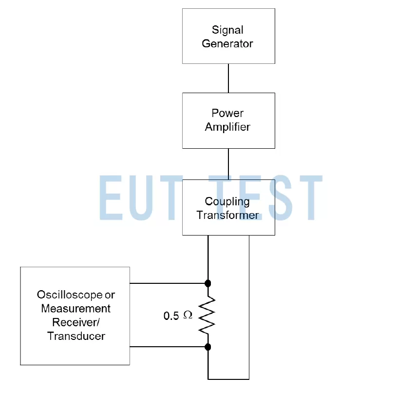
CS101 Calibration Configuration Chart
DUT CS101 Certification Test:
When conducting a formal EUT-CS101 test, the entire EUT should be laid out in the GJB standard configuration shown below as required by the standard to ensure repeatability of the test.
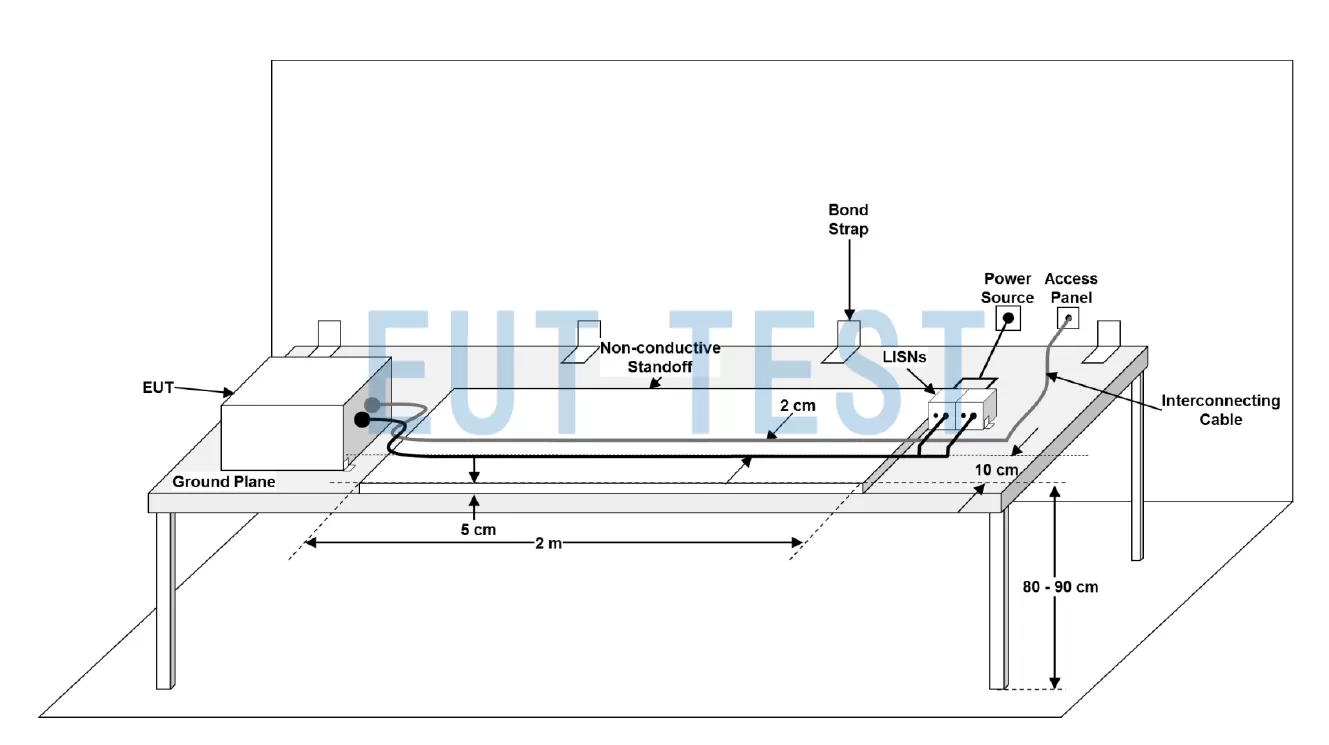
Military DUT test layout
When the basic configuration is completed according to the above diagram. Then connect the CS101 test instrument according to the following single-phase or three-phase EUT test configuration diagram, and then start the test according to the following process.
- Turn on the equipment under test (EUT) and run it for a sufficient period of time before starting the test. CAUTION: Due to the use of an isolation transformer, the oscilloscope's “safety ground” has been disconnected, so care should be taken when performing this test, as there may be a risk of electric shock.
- Open the test software provided by EUTTEST and turn on the test, the software will automatically control the signal source to start increasing the output power.
- After reaching and maintaining the CS101 limit level, the sweep measures the entire desired frequency range.
- Monitor the performance degradation of the device under test. If sensitization occurs, threshold levels need to be determined.
- Repeat the above steps for each power line as required. For three-phase delta power supplies, it is necessary to measure the voltages of the different phases.
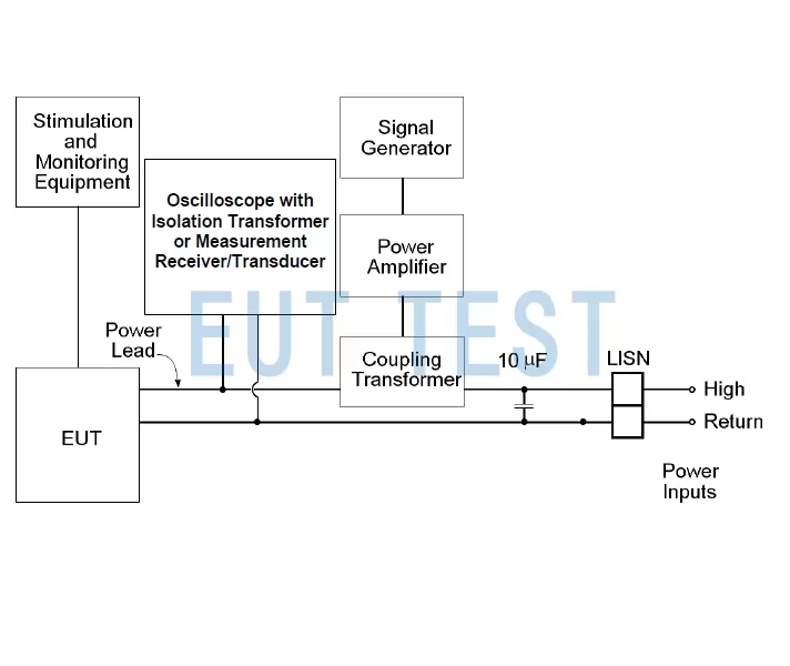
CS101 Test Configuration Diagram for Single Phase Products
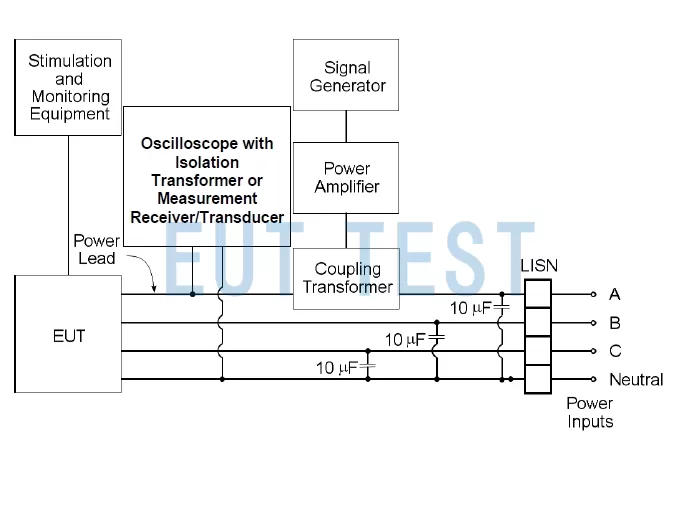
CS101 Test Configuration Diagram for Three-Phase Y-Products
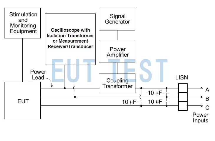
CS101 Test Configuration Diagram for Three-Phase Delta Products
Generate test reports:
We offer EMC test software that provides the following data:
- Provides graphical or tabular data showing the frequency and amplitude of tests performed on each lead.
- Provide data on any sensitivity thresholds and corresponding frequencies for each power lead.
- Provide an indication that each conductor meets the applicable requirements for sensitivity assessment as specified in 5.7.3.4c.
Summary:
The above is the introduction of CS 101 EMC test standard for military electronic products, welcome to contact us for technical solutions and quotation information.
 Introduction to EMC Test Items Required by MIL-STD-461F Standard