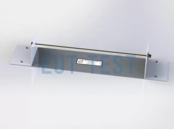
Product Description:
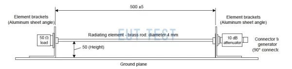
The RS 9244 is a radiated source antenna for automotive electronics manufactured by Schwarzbeck, Germany, and is specifically designed for use in the “long wire antenna method” test proposed in CISPR 25 Ed.4, which requires the use of the long wire antenna method and evaluation of shields with absorbing liners as a radiated source (Airwaves Darkroom ALSE) applicability. The radiating antenna consists of a 500 mm long, 4 mm diameter horizontal brass rod supported by two aluminum supports at a height of 50 mm above an aluminum ground plane with dimensions of 150 mm x 700 mm. For the “long wire antenna method” you need a 10 dB (50 Ohm) attenuator (e.g. Schwarzbeck). DGA 9552 N) as well as a 9244 antenna, and a 90° angle connector.
- Angled connectors help to secure the RF source cable at an angle of 90°.
- On the load side of the RS 9244, a 50 ohm RF load is connected to the end of the rod.
- Angled connectors, 50 ohm RF loads and attenuators are not included in the delivery
Technical parameters:
Product Specification Sheet:
“Reminder: swipe tables left and right”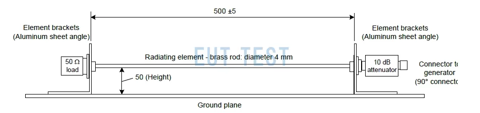
Product Dimension Drawing
Expanding Knowledge:
CISPR25 proposes two ALSE test methods:
In component testing, the measured electric field shall reflect only the characteristics of the equipment under test (EUT) and shall minimize the effects of the ALSE. If measurements are made at different ALSEs and/or at different locations, the variation in the measured data of the EUT shall be as small as possible. Therefore, the effect of ALSE needs to be controlled and ALSE that meets this requirement will have less deviation in the data of the subject equipment.
This appendix contains the ALSE validation requirements for component testing. A total of two procedures are included, both of which can be used for the validation of auxiliary landing equipment (not mandatory for both methods), and a flow chart of the ALSE validation process is shown in the figure below.
The validation procedure is specified as follows:
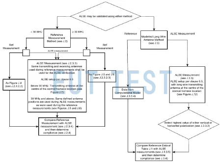
CISPR25 ALSE Long Wire Antenna Method Validation process
Reference measurements:
The method uses a reference test site for reference measurements. A reference test site is an outdoor anti-reflective test site (OATS) or an alternative test site (e.g., weather-proofed outdoor anti-reflective test site or semi-electrical darkroom) that meets the requirements of CISPR 16-1-4:2010/AMD1:2012, clauses 5.4.5 or 5.4.6. Reference measurements are similar to normalized site attenuation (NSA) measurements and are performed on a reference test site with a standard ground plane (site or ALSE floor ground plane up to 30 MHz, and an elevated validated reference ground plane of 2.5 m x 1 m for 30 MHz and above). The corresponding measurements were then performed in the ALSE. The reference measurements are compared to the ALSE measurements to determine if the ALSE measurements are within the specified tolerances.
The long antenna method:
The method uses a 50-centimeter “long wire” antenna as the transmitter antenna. At frequencies below 30 MHz, the long wire antenna is modeled using a ground (non-overhead) ground plane. At frequencies of 30 MHz and above, the long wire antenna is modeled using an overhead validated reference ground plane of standard dimensions (2.5 m x 1 m). Measurements of the long wire antenna were made in the Airborne Laser Ranging System (ALSE). The measurements from the airborne laser ranging system were compared to the modeled field to determine if the measurements from the airborne laser ranging system were within the specified tolerances.
Both the Reference Measurement Method and the Modeled Longline Antenna Method use a standard-sized validated reference ground plane for reference measurements and modeling. At frequencies below 30 MHz, ground (non-overhead) ground planes are used as standard (e.g., the ground surface of an Automated Laboratory System (ALSE), Open Area Test System (OATS), or other test site). The decision to use the same type of validated reference ground plane for both methods was based on the reference [Dr. Luke Turnbull, Ground Plane Resonance - Issues in the Measurement of Radiated Emissions Below 30 MHz, Automotive EMC Conference, Newbury, UK, 2007 (http://www.conekt. co.uk/news-and-events/92-emc-groundplane-paper)], which investigated standard environments using Transverse Electromagnetic Wave (TEM) units and found that the results were the same as those obtained from measurements using the ground plane method. At frequencies above 30 MHz, an overhead validated reference ground plane with dimensions of 2.5 m × 1 m was used as standard. The dimensions and grounding method of the verification reference ground plane used in the reference measurement and modeling process will be different from those used in the laboratory for equipment under test (EUT) measurements in an automated laboratory system (ALSE). Not all Automated Laboratory Systems (ALSE) are constructed and set up the same and will therefore differ to some degree from the standardized verification reference setup. The purpose of this validation procedure is to compare the standardized validation reference setup data (either measured or modeled) with the results of the Automated Laboratory System (ALSE) used to perform CISPR 25 radiated emission testing of the Equipment Under Test (EUT) to ensure that deviations due to differences in the settings of the Automated Laboratory System (ALSE) are within reasonable tolerances.
Order No. EUTS0873
EUTTEST is an official authorized distributor of SCHWARZBECK, whose full official name is: SCHWARZBECK MESS - ELEKTRONIK OHG
Ltd. is authorized by schwarzbeck to sell all products in China and provide technical service for the products sold.


 Schwarzbeck Product List Schwarzbeck
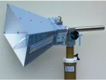 BBHA 9120 D Schwarzbeck
 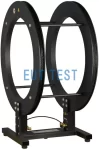 Helmholtz coils Schwarzbeck
  ETS 6512 ETS-Lindgren
 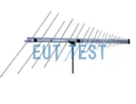 ETS 3144 ETS-Lindgren
 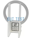 FESP 5133-F Schwarzbeck
  VULB 9163 Schwarzbeck