
This article explains the differences between the three industry standard conducted emission CE limits and test setups for automotive electronics CISPR 25, industrial CISPR 11 and defense applications MIL-STD-461 respectively. This is the second part of the article, which focuses on the differences between the three industry standard limit lines for EMC testing, and test setups.
It is recommended that you first understand the three standard conduction test EMC test standard differences, test setup differences and other content in the re-read this article, reference content:
CISPR 25 (voltage and current method)
Figure 4 shows the CE interference limits for CISPR 25 5 Class 5 PK and AV in the service bands for broadcast and mobile when using voltage and current test methods. The red and blue lines indicate the PK and AV detectors, respectively.
Since the mounting location, body structure and harness design can affect the level of interference to in-car radio receivers, CISPR 25 specifies several limit levels, with Category 5 being the most stringent. 4, 3, 2 and 1 have incremental limits of 6-10 dB.
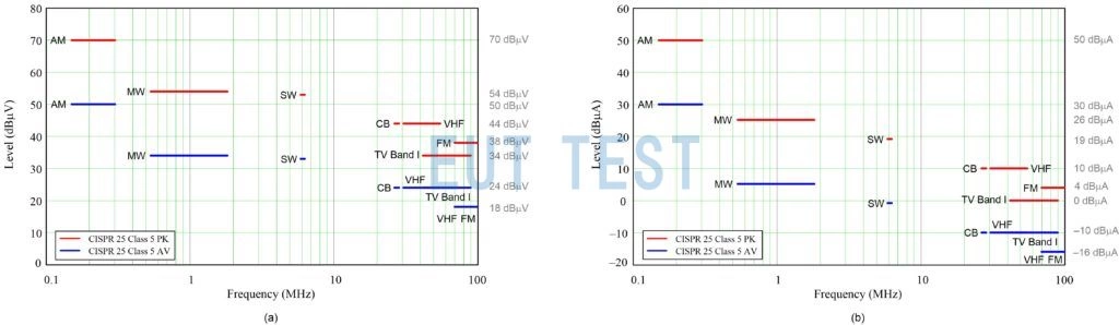
Figure 4: CISPR 25 Category 5 PK and AV limits for conducted nuisance: voltage method (a); current method (B).
Figures 5 and 6 show the CISPR 25 recommended test setups for voltage method and current method CE tests, respectively. This standard defines the configuration of the system under test as well as the measurement scheme and equipment. TheLISNDesignated as AN by CISPR 25. the AN is mounted directly on the reference ground plane and the AN housing is soldered to the ground plane. The power circuit is also connected to the grounding layer between the power supply and the AN.
For the voltage method test shown in Figure 5, when the vehicle power return line length is greater than 200 mm, the EUT is remotely grounded and two ANs are required: one for the positive power line and one for the power return line. On the contrary, if the vehicle power return line is 200 mm or shorter, the EUT is locally grounded and only one AN is required for the positive power supply.Connecting the EMI receiver to the measurement port of the corresponding AN allows successful measurement of the radiation conducted on each power line. At the same time, a 50 Ω load termination is inserted into the AN port of the other power line. The power line is connected to a non-conductive low relative dielectric constant material (e.g. r<1.4), located 50 mm above the reference grounding layer.
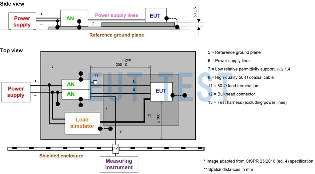
Figure 5: Overview of the CISPR 25 conducted EMI test setup (voltage method). The power supply return is shown as remotely grounded.
For the current methodology, the test setup shown in Figure 6 simulates an actual vehicle configuration that specifies the electrical connection of the remote to local ground and the EUT enclosure to the reference ground plane.The current probes as defined in CISPR 16-1-2 are installed around the complete wiring harness including all wires and are located at two locations 5 cm and 75 cm from the EUT. The shielded wiring harness used for this test is representative of a vehicle application in terms of cable construction and connector termination, as defined in the test plan.

Figure 6: Overview of the CISPR 25 conducted EMI test setup (current method).
CISPR 11 & GB4824
CISPR 11 and GB4824 Involves controlling RF interference from ISM equipment by evaluating these interferences at a standardized test site or, for individual ISM RF applications that cannot be tested at such a site, at their place of operation (in the field). For the purpose of determining the relevant limits, the equipment within the scope of this standard is divided into two groups:
- Group 1Includes all equipment within the scope of CISPR 11 that is not categorized as Group 2 equipment (examples include semiconductor manufacturing equipment, machine tools, and industrial process measurement and control equipment). See CISPR 11 Annex A for further details.
- Group 2Includes all ISM devices where RF energy in the frequency range of 9 kHz to 400 GHz is intentionally generated and used locally. Examples include arc welders and wireless power transfer systems.
In addition, each equipment group has a Class A (non-residential, industrial, commercial) and Class B (residential, consumer) designation and associated restrictions.
Figure 7 shows the CISPR 11 limit lines for Group 1 (AC power and DC power ports) and Group 2 (AC power ports) devices. The red and blue lines refer to the QP and AV detectors, respectively.
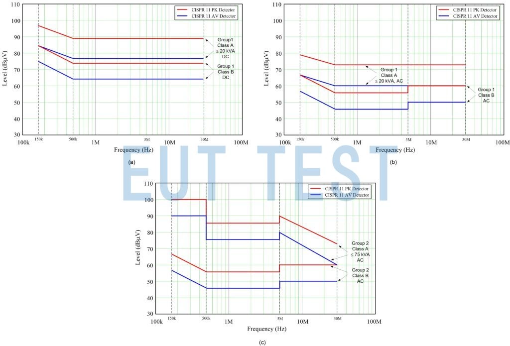
Figure 7: CISPR 11 conducted nuisance limits: Group 1 - DC mains ports (a); Group 1 - AC mains ports (B); Group 2 - AC mains ports (c)
For more see Tables 2 and 5 (Group 1) and Tables 8 and 9 (Group 2) of the CISPR 11 publication [9]. The CE test setup for a bench-mounted EUT is shown in Figure 8.
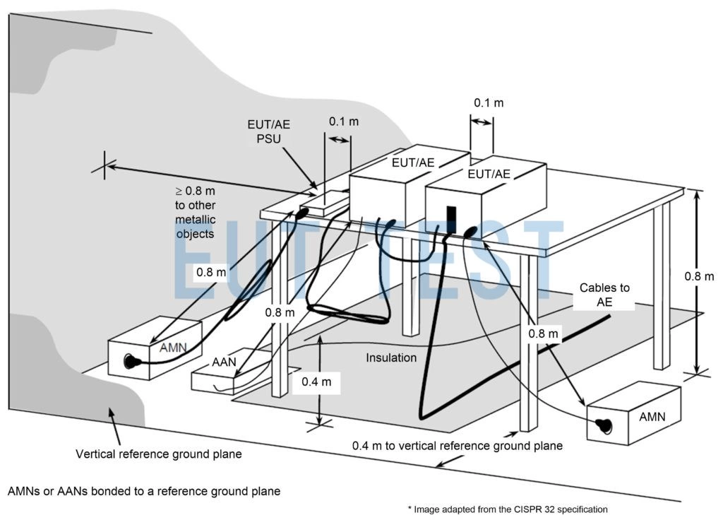
Figure 8: Overview of the conducted EMI laboratory installation test setup for CISPR 11. Note that the spacing to the vertical strata is 0.4 m. The distance from the AMN to the EUT is 0.8 m. The distance from the AMN to the EUT is 0.8 m.
The
MIL-STD-461 (CE 101 and CE 102)
Figure 9 gives the PK detector when using theCE 101(audio current, power cord) andCE 102(RF potentials, power lines) limits. Refer to the MIL-STD-461 specification for a more in-depth understanding of limit relaxation under various conditions.

Figure 9: MIL-STD-461 conducted interference limits: CE101(a); CE102(B).
As shown in Figure 10, 2 m long input power lines (including zero and loop) are parallel to the leading edge of the CE 101 and CE 102 test setups in MIL-STD-461. Each input power line is connected to the LISN.
In a practical installation, the power cables bundled together as part of the interconnecting cable are separated from the harness and routed outside the LISN-shielded cable shield. After an exposure length of 2 m, the power cables terminate at the LISN over the shortest possible distance. the total length of the power cables from the EUT's electrical connectors to the LISN should not exceed 2.5 m - except for the large EUT shown in Fig. 10 b, in which the cables are routed from the top of the high EUT or from the bottom of the floor-to-ceiling cabinet. In this case, the total length can exceed 2.5 m but still remain minimal. All power cables are supported 5 cm above the ground plane using a non-conductive material (usually foam or wood). If a stranded connection exists in the actual installation, the power cables are stranded to the LISN.
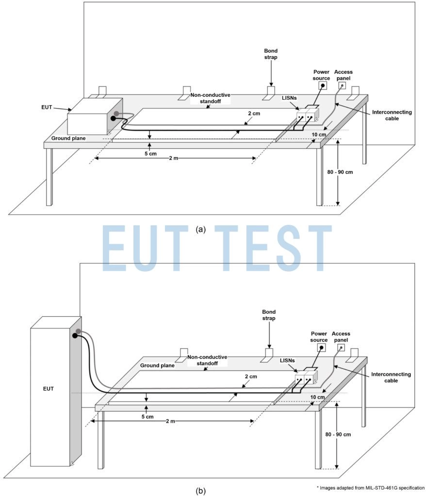
Figure 10: General overview of a MIL-STD-461 G compliant conducted EMI test setup in a shielded enclosure with a desktop EUT (a); freestanding EUT in a shielded enclosure with connections wired from the top of the cabinet (b).
These are the differences between the three industry standard conducted emission CE limits and test setups for automotive electronics CISPR 25, industrial CISPR 11 and defense applications MIL-STD-461.
bibliography
Hegarty Timothy. 2018." Power Supply Conducted EMI Specification Overview." Texas Instruments White, Literature Number SLYY136, February 2018. Hegarty Timothy. 2021." DC-DC Regulator EMI Engineer's Guide." Texas Instruments eBook, Chapter 1, Q2 2021 (TBD). Chaluwadi, Mahesh, G. Vincentraj, and K. George Thomas. " A Comparative Study of Conducted Emission Tests in International EMC Standards." Presented at the IEEE International Conference on Power, Control, Signal, and Instrumentation Engineering, Sept. 2017 pp. 21-22. 1352-1355. Chaluwadi, Mahesh, G. Vincentraj, and K. George Thomas. " An in-depth look at MIL-STD-461 G: A research report." Presented at the IEEE International Conference on Power, Control, Signal, and Instrumentation Engineering, Sept. 2017. pp. 21-22. 1356-1359. " Vehicles, Boats, and Internal Combustion Engines. Radio Interference Characterization . Limits and measurement methods for on-board receiver protection ." CISPR 25:2016, 4th edition (or EN 55025:2017).CISPR: Geneva, Switzerland, October 2017.CISPR: Geneva, Switzerland. " Industrial, Scientific and Medical Equipment . RF Interference Characterization . Limits and methods of measurement ." CISPR 11:2015, Sixth Edition.CISPR: Geneva, Switzerland, January 2019. "Requirements for Control of Electromagnetic Interference Characteristics of Subsystems and Equipment..." MIL-STD-461 G, U.S. Department of Defense Interface Standard: Washington, DC, December 2015. Javorkian. 2018." E Pluribus Unum - Reviewing the Fifty Years of MIL-STD-461." Interference Technology Magazine, 2018 Catalog and Design Guide. " Industrial, Scientific, and Medical Devices. RF Interference Characterization . Limits and methods of measurement ." IS EN 55011:2016, European normative standard based on CISPR 11. European Committee for Electrotechnical Standardization (CENELEC): 2016, Brussels, Belgium. " Electromagnetic compatibility (EMC) - Part 6-4: General standard. Emission standards for industrial environments ." IEC 61000-6-4, 3rd ed. IEC: February 2018, Geneva, Switzerland. " Specification for radio nuisance and immunity measurement devices and methods - Part 1-2: Radio interference and immunity measurement equipment . Coupling devices for conducted interference measurements." CISPR 16-1-2: 2014. cispr: August 2020, Geneva, Switzerland. " Specification for Radio Nuisance and Immunity Measurement Devices and Methods-Part 2-1: Methods for Measurement of Interference and Immunity . Conducted interference measurements ." CISPR 16-2-1: 2014. CISPR: Geneva, Switzerland, June 2017. "2020 Automotive EMC Guidelines. Interference Technology Magazine, May 2020. The 2020 Medical EMC Guide. Interference Technology Magazine, September 2020 Ferguson, Steve. 2020." MIL-STD-461 G and RTCA/DO-160 G Test Configuration Management." 2020 Military and Aerospace EMC Guide, Interference Technology Magazine, December 2020, pp. 8-12.
Originally Posted by Timothy Hegarty, Applications Engineer, Texas Instruments