
This article is the first part of the conducted emission differences for automotive, industrial and defense applications. We have compiled and illustrated the differences in EMC-CE testing for the three industry standards of CISPR 25 for automotive electronics, CISPR 11 for industrial, and MIL-STD-461 for defense applications, respectively, including the requirements of EMC testing standards for different industries, product applicability, LISN, EUT and LISN, EUT and LISN settings, voltage method and current method and other testing differences.
We use the following three widely used specialized standards to compare and illustrate the differences in conducted emission testing for automotive, industrial and defense applications:
- International Special Committee on Radio InterferenceCISPR 25Edition 4 (2016), Product standard for the protection of on-board receivers in vehicles, ships and internal combustion engines [5].
- CISPR 11Edition 6 (2015), Product standards for industrial, scientific and medical (ISM) devices [6] that use radio frequency (RF) energy to perform their intended functions.
- and military standards from 2015MIL-STD-461Revision G (Defense Standard for Equipment and Subsystem Enclosures) [7-8].
CISPR has Subcommittees B and D for CISPR 11 and 25, respectively, while the U.S. Department of Defense is responsible for MIL-STD-461.The European Union has adopted CISPR 11 and CISPR 25 as EN 55011 [9] and EN 55025, respectively.CISPR 11 is used as the basic test method for generic, product and product family emission standards, such as the Generic for Industrial Environmental emission standards, International Electrotechnical Commission (IEC) 61000-6-4 [10].
Comparison of CE test setups and test methods for different industries:
Different standards define different product suitability and test frequency ranges
Components and modules for in-vehicle automotive applications according to CISPR 25 are tested in the total frequency range from 150 kHz to 108 MHz to protect in-vehicle receivers in the service bands of broadcast and mobile.
Testing in the CISPR Band B frequency range of 150 kHz to 30 MHz meets the CE requirements for products manufactured in ISM applications, as required by CISPR 11 (or FCC Part 18).
In MIL-STD-461 G, CE 101 and CE 102 tests are performed in the frequency ranges of 30 Hz to 10 kHz and 10 kHz to 10 MHz, respectively, to fulfill CE requirements. These tests are performed on the power line, including the circuit of the equipment under test (EUT) that receives power from an external (grid or DC) supply. The applicability of the tests depends on the intended installation environment of the equipment.
Different CE test equipment for different industries - LISN.
When not discussing test standards, generally the main test equipment we need to perform CE testing includes:
- EMI Receiver or Spectrum Analyzer - Equipped with appropriate Peak (PK), Quasi-Peak (QP) or Average (AV) detectors as defined in CISPR 16-1-1.
- Line Impedance Stabilization Networks LISN-also known asArtificial Power Network AMN, artificial network AN or V-network.
- Current Probe-Required for current method testing in CISPR 25 and CE 101 testing in MIL-STD-461 only.
More specifically, the LISN is a passive network that provides a well-defined and constant terminating impedance (close to 50 Ω) through the EUT power terminals over the applicable test frequency range specified in each standard. It is also useful to isolate the EUT from ambient noise on the corresponding AC or DC power line over the test frequency range.The RF port of the LISN is connected to the 50 Ω input port of an EMI receiver to measure the noise generated by the EUT.
Table 1 details the applicable frequency ranges for different applications. The table includes a comparison of various test parameters such as test frequency range, LISN network type, test equipment and test setup requirements.

Table 1: Comparison of various specifications and parameters for CE testing based on CISPR 25, CISPR 11 and MIL-STD-461.
The measurement receiver should be capable of scanning over the desired test frequency range with the appropriate resolution bandwidth (RBW) provided in the appropriate standards for the different applications. For this purpose, the detector type, RBW, measurement step and dwell time parameters of the EMI receiver are given in Table 2.

Table 2: Comparison of EMI receiver settings for CE testing according to CISPR 25, CISPR 11 and MIL-STD-461.
The LISN networks specified in different standards are different because of the different test frequency ranges. Figures 1, 2 and 3 show the network schematics and nominal impedance curves for LISNs used for CISPR 25, CISPR 11 and MIL-STD-461 measurements, respectively. The LISN for CISPR 11 in Fig. 2 is a V-type network (V-AMN) as specified in CISPR 16-1-2 [11] for line-to-ground asymmetric mode emissions from the power ports of low-voltage AC networks.
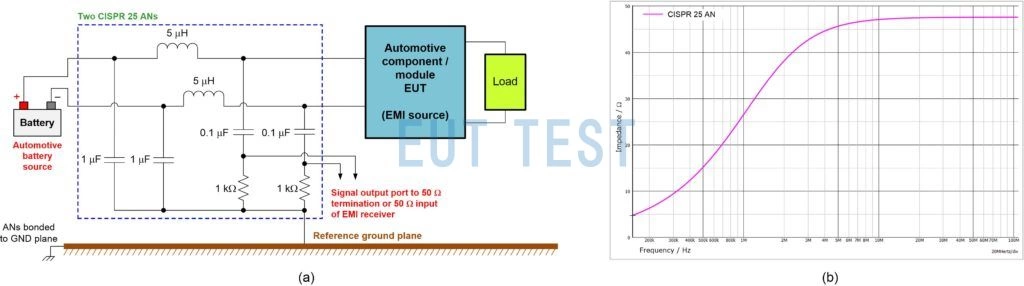
Figure 1: Schematic of CISPR 25 (a) and nominal impedance characteristics from 150 kHz to 108 MHz (B).
(The use of a dedicated 150 Ω artificial power Δ network as specified in CISPR 16-1-2 clause 4.7 [see also Figure A.2 in CISPR 16-1-2] or a 150 Ω artificial DC network [DC-AN] as specified in CISPR 11 Appendix I facilitates the measurement of disturbance voltages at the low-voltage DC power ports [e.g., for grid-connected solar inverters] in CISPR 11.) Both devices couple interline or symmetrical (differential mode) and asymmetrical (common-mode) voltage disturbances, respectively, and each disturbance mode can usually be selected as desired via a switch.
In general, terminating the measurement port with a 50 Ω load produces an impedance of LISN between the output and ground (as shown in Figures 1, 2 and 3). This normalized impedance represents the expected impedance in an actual installation.
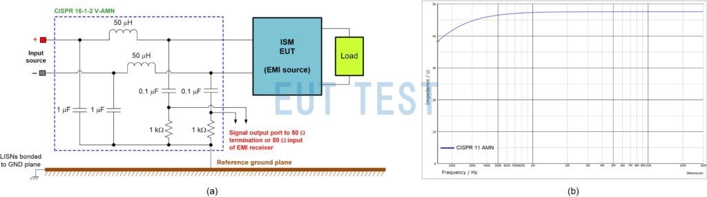
Figure 2: AMN schematic for CISPR 11 (a) and nominal impedance characteristics from 150 kHz to 30 MHz (B).

Figure 3: LISN schematic (a) and MIL-STD-461 nominal impedance characteristics from 10 kHz to 10 MHz (B).
The LISN inductance of 50 µH represents the inductance of a distribution line with a wiring length of approximately 50 m. This value is quite representative for large platforms (freighters or industrial systems). For large platforms (e.g. cargo planes or industrial systems), this value is fairly representative of the actual installation. For smaller platforms with shorter distribution line lengths (e.g., fighter jets), the inductance may be much lower than 50 µH.
MIL-STD-461 specifies the use of a default 50 µH LISN as shown in Figure 3-a, but also supports the use of a 5-µH LISN for certain applications where high current loads are present, where distribution circuit lengths are short, or where dedicated circuits are connected to high-end power supplies (as opposed to structural circuits) (similar to Figure 1a). In these cases, the 5-µH LISN must be approved by the purchasing department with the necessary adjustments to the CE 101 test limits.
Meanwhile, automotive applications use a low inductance LISN of 5 µH because it simulates the typical inductance of an automotive harness setup.
The grounding layer is made of copper, brass, bronze, or galvanized steel and is electrically connected to the wall or floor of the shielded enclosure so that its DC resistance does not exceed 2.5 mΩ. The minimum dimensions of the grounding layer, according to the CISPR 25 Voltage Method, the CISPR 25 Current Method, CISPR 11, and the MIL-STD-461 standard are specified as 1 m x 0.4 m, 2.5 m x 0.4 m, 2 m x 2 m, 2 m x 2 m, 2 m x 2 m, 2 m x 2 m, 2 m x 2 m, and 2.25 m, respectively. and 2.25 m2The
Different EUT and LISN placements
The EUT was placed in a non-conducting, low relative dielectric constant material (er≤ 1.4) on the EUT at a height of (50 ±5) mm above the reference ground plane according to CISPR 25 and MIL-STD-461, and at a height of 400 mm above the ground plane according to CISPR 11 (for non-floor-mounted equipment). If connected in the actual installation, the EUT shall be connected to the ground plane. the LISN is mounted on the ground plane and is electrically connected to it.
Difference between voltage or current method
There are two possible methods for performing the CE test: the voltage method and the current method. When using the voltage method of testing, the LISN is connected to the power line under test and acts as a sensor; its RF measurement port is connected to the input port of the measurement receiver. The RF port of the other LISN in the test setup is terminated with a 50 Ω load. In the current method test, the current probe is clamped to the power supply lead under test and acts as a sensor to measure the noise current flowing through the lead.
The CISPR 25 standard allows for either voltage or current method testing.The CISPR 11 standard requires voltage method testing at power levels below 20 kVA.The CE 101 and CE 102 tests in MIL-STD-461 use current method and voltage method testing, respectively.
For all tests, measure the conducted EM ambient level before performing the test with the EUT powered off and all auxiliary equipment on. It shall be at least 6 dB below the allowable specified limit.
Differences in the arrangement and length of power cords
The power cord from the EUT to the LISN power port is placed on a non-conductive support at a height of 50 mm above the reference ground plane for CISPR 25 and MIL-STD-461.
Using the voltage test method, the power supply leads are 0.2 m, 1 m and 2 m long, as defined in the CISPR 25, CISPR 11 and MIL-STD-461 standards. When using the current method, the cable bundle extends 1.7 m long according to CISPR 25 (or as agreed in the test plan). Unless otherwise specified in the test plan, the test harness wires shall be set to be nominally parallel and adjacent.MIL-STD-461 CE 101The power cord for the test program extends at least 2 m and the current probe of the CE 101 is located 5 cm from the LISN.
Difference between detectors
CISPR 25 uses PK or QP and AV detectors, CISPR 11 uses QP and AV detectors, and MIL-STD-461 requires PK detectors to perform CE testing.
Continue reading:Conducted Emission Distinctions for Automotive, Industrial and Defense Applications - Part II - CE Limits and Test Setups
bibliography
Hegarty Timothy. 2018." Power Supply Conducted EMI Specification Overview." Texas Instruments White, Literature Number SLYY136, February 2018.
Hegarty Timothy. 2021." DC-DC Regulator EMI Engineer's Guide". Texas Instruments eBook, Chapter 1, Q2 2021 (TBD).
Chaluwadi, Mahesh, G. Vincentraj, and K. George Thomas. " A Comparative Study of Conducted Emission Tests in International Electromagnetic Compatibility Standards." Presented at the IEEE International Conference on Power, Control, Signal and Instrumentation Engineering, Sept. 2017. pp. 21-22. 1352-1355.
Chaluwadi, Mahesh, G. Vincentraj, and K. George Thomas. " An in-depth look at MIL-STD-461 G: A research report." Presented at the IEEE International Conference on Power, Control, Signal, and Instrumentation Engineering, Sept. 2017. pp. 21-22. 1356-1359.
" Vehicles, boats and internal combustion engines. Radio Interference Characterization . Limits and measurement methods for on-board receiver protection ." CISPR 25:2016, 4th edition (or EN 55025:2017).CISPR: Geneva, Switzerland, October 2017
" Industrial, Scientific and Medical Equipment. RF Interference Characterization . Limits and methods of measurement ." CISPR 11:2015, Sixth Edition.CISPR: Geneva, Switzerland, January 2019
"Requirements for Control of Electromagnetic Interference Characteristics of Subsystems and Equipment..." MIL-STD-461 G, U.S. Department of Defense Interface Standards : Washington, D.C. December 2015
Javorkian. 2018." E Pluribus Unum - Reviewing Fifty Years of MIL-STD-461." Interference Technology Magazine, 2018 Catalog and Design Guide.
" Industrial, Scientific and Medical Equipment. RF Interference Characterization . Limits and methods of measurement ." IS EN 55011: 2016, European normative standard based on CISPR 11. European Committee for Electrotechnical Standardization (CENELEC): 2016, Brussels, Belgium.
" Electromagnetic Compatibility (EMC) - Part 6-4: General Standard. Emission standards for industrial environments ." IEC 61000-6-4, 3rd ed. IEC: Geneva, Switzerland, February 2018.
" Specification for radio nuisance and immunity measurement devices and methods - Part 1-2: Radio interference and immunity measurement equipment. Coupling devices for conducted interference measurements ." CISPR 16-1-2: 2014. cispr: August 2020, Geneva, Switzerland. " Specification for Radio Nuisance and Immunity Measurement Devices and Methods-Part 2-1: Methods for Measurement of Interference and Immunity . Conducted interference measurements ." CISPR 16-2-1: 2014. CISPR: June 2017, Geneva, Switzerland.
The 2020 Automotive EMC Guide. Interference Technology magazine, May 2020. The 2020 Medical EMC Guide. Interference Technology Magazine, September 2020
Ferguson, Steve. 2020." MIL-STD-461 G and RTCA/DO-160 G Test Configuration Management." 2020 Military and Aerospace EMC Guide, Interference Technology Magazine, December 2020, pp. 8-12.
Originally Posted by Timothy Hegarty, Applications Engineer, Texas Instruments