
Introduction:
This page summarizes how our military standard GJB151B-2013 selects the correct test arrangement method based on the DUT. Unless otherwise specified.GJB151B-2013 All Test ItemsThe EUT in the DUT should be built in a test configuration according to Figure 1 - Figure 5.
We provide our customers with GJB151B-2013 compliantEMC test equipment and system solutionsAll test configurations we offer are suitable for the following test programs. Of course the test requirements of the older standards GJB 151A, GJB152A, MIL-STD-461G are also applicable.
GJB151B-2013 All test item forms:
“Reminder: swipe tables left and right”GJB151B-2013 All test layout drawings:
EMC test items are the basic content of GJB151B-2013, but all test items need to rely on the following introduction of the test layout diagram to make the EUT test environment in line with the standard test requirements, see below for more details on the introduction of the dark room and shielded room environment of the desktop equipment, ungrounded equipment, floor-standing equipment, the different test layout method.
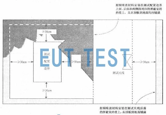
GJB151B-2013 Fig. 1 Installation of RF absorbing materials
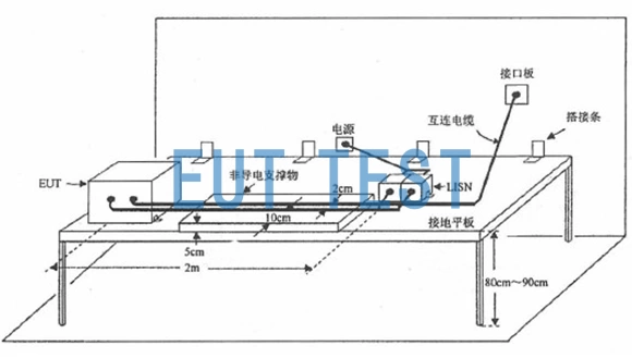
GJB151B-2013 Figure 2 General Test Configuration
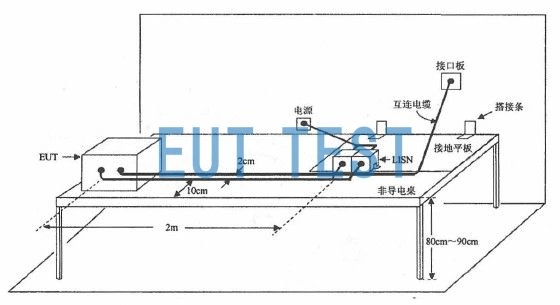
GJB151B-2013 Figure 3 Test Configuration for Placing an EUT on a Non-Conductive Surface
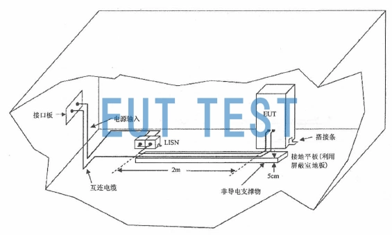
GJB151B-2013 Figure 4 Test Configuration for Floor-Mounted EUTs in Shielded Rooms
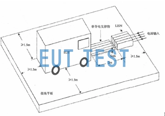
GJB151B-2013 Figure 5 Test Configuration for Floor-Mounted EUTs
The above is the GJB151B-2013 how to choose the right test layout according to the DUT related content, in order to implement EMC test for your products as soon as possible, you can contact EUTTEST Procurement of EMC instrumentationCarry out the test and you can also check out:
GJB151B-2013 Requirements for the arrangement and working condition of the EUT.