
In the field of Electromagnetic Compatibility (EMC), as a result of the factors that cause The Three Elements of the EMC ProblemFor the noise source (source), path (path) and victim (victim), how to do electromagnetic compatibility EMC electromagnetic shielding design has become the focus of circuit design, electromagnetic shielding is the role of electromagnetic energy can be cut off from the air transmission path to eliminate electromagnetic interference. Good shielding design, can effectively reduce the noise radiation on the car electrical equipment, can also reduce the external electromagnetic noise on the car electrical equipment. Modern vehicle design, in order to reduce the weight and enhance the mechanical characteristics of the body structure or vehicle components gradually tend to change to more complex electrical composite materials (such as in the non-conductive parent material plus conductive or highly conductive additives, conductive carbon black, essential conductive polymers, advanced composite materials, ... and so on) to replace the metal. As the conductivity of the composite material is not as good as metal, its electromagnetic shielding efficiency (SE; shielding effectiveness) will change. In addition, the vehicle components there are heat dissipation, line access or window holes (aperture), these holes will also affect the overall shielding effect. Therefore, the selection of shielding materials and the design of apertures are very important key technologies in shielding countermeasures.
EMC electromagnetic shielding design - Selection of shielding materials
Shielding efficiency (SE; shielding efficiency) is the parameter that determines whether the shielding is good or not and is defined as:
SE(dB) = 20 log(E1/ E2 )
included among theseE1 is the electric/magnetic field strength at the observation point when the noise source is not shielded, and theE2 It is the electric/magnetic field strength at the observation point after the noise source is shielded, and the ratio of the two is logarithmically calculated to be the shielding efficiency (SE) of this shielding measure.
For example, for EMC testingelectromagnetic shielding roommaybeAnechoic chamber, all of which use the above formula to calculate the dark indoor/outdoorSE(dB) Shielding effectiveness.
Since the properties of electromagnetic wave radiation can vary depending on the near and far fields, the general critical distance between near and far fields can be expressed as:
d=λ/2π and the critical frequency can be expressed as f0=c/2πd
included among theseλis the wavelength (m),c is the speed of light (v/m). The critical frequency f0 is 47.7 MHz for a test distance of 1 m, which is commonly used in vehicles. f> f0 is a far-field plane wave when f < f0 for near field.
The near-field can be divided into electric field and magnetic field phenomena. The near-field electric field radiation source is a noise source with high voltage and low current characteristics (high impedance), while the near-field magnetic field radiation source is a noise source with low voltage and high current characteristics (low impedance). The wave impedance of the far-field plane wave is 377 Ω, which can be regarded as the critical value between high impedance and low impedance, compared to the near-field electric/magnetic field radiation source. For different characteristics of the radiation of electromagnetic waves, the same material shielding material will produce different effects, so how to choose the appropriate shielding material is very important.
As shown in Figure 4.1, the shielding efficiency of a shielding material can be expressed asSE(dB)= R + A+ B which R Losses caused by reflection of electromagnetic waves on the surface of the shielding material, so it is called reflection loss; A is the loss that occurs when electromagnetic waves propagate within the shielding material, so it is called absorption loss and B is then the multiple reflection correction factor. Since the effect of multiple reflections has a limited impact, it can be simplified asSE =R +A The higher the value of reflection loss and absorption loss, the better the shielding efficiency of the material. This shows that the higher the value of reflection loss and absorption loss, the better the shielding efficiency of the material.
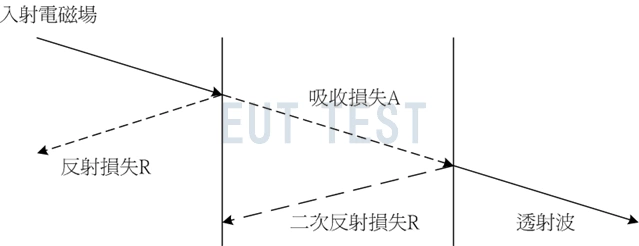
Figure 4.1 Important parameters of shielding materials for EMC electromagnetic shielding design
reflective loss
The reflection loss of the shielding material must be considered separately for the effects of magnetic field, electric field and plane wave, which can be expressed by the calculation equation:
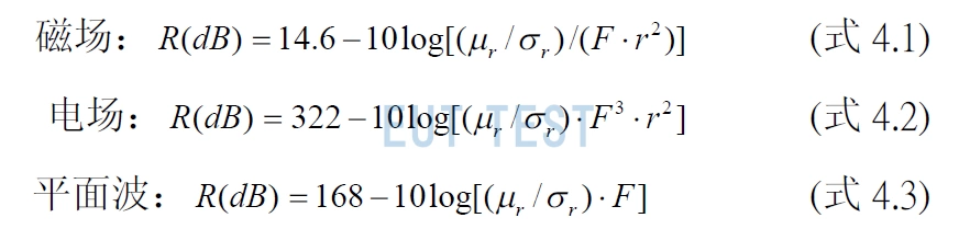
Reflection loss formula for magnetic and electric fields and plane waves
where F is the frequency (Hz), r is the distance from the observation point (m).μr is the relative permeability and is the electrical conductivity.
Based on the above equation the conclusion can be drawn:
Reflection loss is a function of the material's permeability and electrical conductivity, and materials with high electrical conductivity (e.g., copper, aluminum) have high reflection loss.
Reflection loss is related to the characteristics of electromagnetic wave radiation, so changes in the distance from the shield to the radiation source will affect the size of the reflection loss. For electric field radiation source (high impedance), if the closer to the electric field radiation source, because the electromagnetic energy impedance is greater, so the reflection loss is also greater. However, the opposite is true for magnetic field radiation sources (low impedance). Therefore, for shielding of electric field sources, the shield should be as close to the source as possible, while for magnetic field sources, the shield should be as far away from the source as possible. However, as the frequency increases, the reflection loss will have nothing to do with the characteristics of electromagnetic wave radiation, the observation point distance. This is because when the frequency is raised to the critical frequency of the near and far fields, the wave impedance of the electric/magnetic field radiation source will be equivalent to the wave impedance of the plane wave in the far field, and at this time, the wave impedance will be maintained at about 377Ω.
Since the reflection loss is also a function of frequency, for magnetic fields (high impedance), the reflection loss increases as the frequency is raised; for electric fields (low impedance), plane waves, it decreases as the frequency is raised.
Since the reflection loss does not lose electromagnetic energy, but reflects it. Therefore, for EMI shielding, the reflection loss of the shielding material must not be too high, as the reflection of electromagnetic waves from a high noise source through the shielding may interfere with other neighboring and more sensitive components inside. For EMS shielding, however, it is not necessary to consider whether the reflection loss is too high.
absorption loss
Since the absorption loss can be expressed as: A(dB) = 8.69(t/δ) (equation 4.4)
where t is the thickness of the shielding material (mm); is the skinning depth, expressed as δ = 0.66/√(μσf(MHz))
The following conclusion can be drawn from equation 4.4:
Absorption loss is related to the skinning depth, the deeper the skinning depth, the smaller the absorption loss. Skinning depth is related to the material properties, the shielding material's permeability and electrical conductivity, the higher the permeability or electrical conductivity, the smaller the skinning depth; and as the frequency increases, the skinning depth of the same material will become smaller. However, due to the limited increase in electrical conductivity of metallic materials, materials with high permeability are usually used to increase absorption losses, as shown in Table 4.1.
“Reminder: swipe tables left and right”coefficient of magnetic permeability
Table 4.1 Skinning depth of commonly used shielding materials
The thicker the shielding material, the higher the absorption loss. From (Eq. 4.4), it can be seen that when the thickness of the shielding material increases by one skin depth, the absorption loss can be increased by 8.69dB.
Absorption losses are independent of the characteristics of the electromagnetic wave radiation (wave impedance) and are the same whether it is an electric field, a magnetic field or a plane wave. This is because the absorption loss is only related to the skinning depth. As shown in Table 4.1, the lower the frequency, the greater the skinning depth of the material.
So the absorption loss will be the smaller, so the electromagnetic energy of low frequency has a strong penetration.
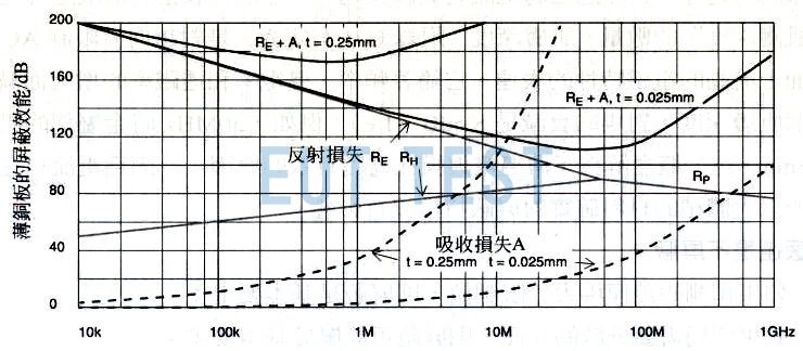
Fig. 4.2 Shielding efficiency of copper plate versus frequency
Overall shielding effectiveness of shielding materials
Comprehensive description of the above can be learned that the absorption loss and reflection loss is an important parameter to determine the shielding efficiency of the material, so in the selection of shielding materials have the following principles:
At low frequencies, the shielding efficiency of the material is closely related to the characteristics of electromagnetic wave radiation (wave impedance). Because of the low-frequency electromagnetic energy skin depth is larger, resulting in lower absorption losses, when the shielding efficiency depends mainly on the reflection loss. The reflection loss and electromagnetic wave radiation wave impedance, the wave impedance of the magnetic field is very low, so the reflection loss is also low, so relative to the low-frequency electric field, low-frequency magnetic field is more difficult to shield, as shown in Figure 4.2.
Shielding efficiency at high frequencies has nothing to do with the characteristics of electromagnetic wave radiation (wave impedance). Because of high frequency electromagnetic energy skin depth is small, absorption loss is high, this time the shielding efficiency mainly depends on the absorption loss. So at high frequencies, for different characteristics of the radiation of electromagnetic waves, shielding material shielding efficiency is almost the same.
Compared to magnetic fields, shielding materials have higher reflection losses to electric fields and higher absorption losses to plane waves, so magnetic fields are the most difficult to shield, especially at very low frequencies, such as 50/60Hz magnetic fields must be additionally used in other shielding methods.
EMC electromagnetic shielding design - hole design of shielding body
In general, most metallic materials can provide shielding efficiencies of 100dB or more, except for low frequency magnetic fields. As the ideal shielding body must be a completely closed shielding body, in order to form a complete, continuous conductive body, to achieve the best shielding effect. However, in practice, completely closed shielding body is of no practical value, because the automotive electronic components must be considered heat dissipation, line in and out or window design, so the impact caused by holes must be considered. Because the hole will destroy the continuity of the conductor, resulting in electromagnetic energy will leak in the hole, reducing the overall shielding effect. So the design of holes, such as hole shape, hole depth (thickness) and opening rate, etc., are very important in the shielding design of the key.
 Two effective ways to attenuate EMI radiation interference