
Introduction:
This article focuses on how to improvespectrum analyzerrespond in singingcurrent probeThe signal-to-noise ratio of the current probe method of measurement, the higher the signal-to-noise ratio, the higher the dynamic range of the entire test system. Spectrum analyzer has many test methods, we only use the current probe test method to analyze how to improve the signal-to-noise ratio of the spectrum analyzer.
Obtain raw data from the spectrum analyzer:
Spectrum analyzers (SAs) generally have noise floors (often referred to as the Displayed Average Noise Level - DANL) listed in their technical data documentation. For example, our company represents and sells R&S FSV Spectrum Analyzer, we can find the DANL data given at one or more specific frequencies for a certain RBW setting value in the document, as shown below:
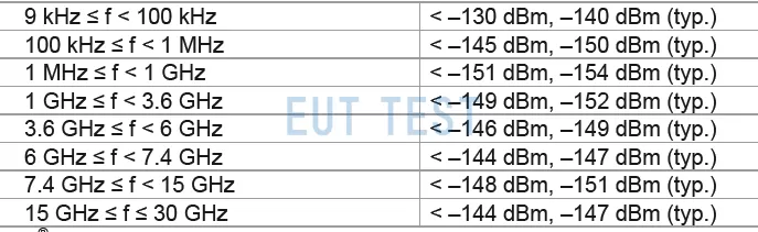
R&S FSV Average Noise DANL at RBW=1kHz
Predicted minimum noise level:
Once the minimum noise data from the spectrum analyzer is obtained, we can predict the minimum noise level for the conducted nuisance test configuration Compare the DANL data given in the figure above, we need to perform the conducted common mode-current method test on different RBWs, and here we can use the following formula to estimate it:
Conducted Emission Current Method Noise Level (dBm) = Spectrum Analyzer Noise Level (dBm) + 10*log(RBW of current method setting/RBW of spectrum analyzer)
From the above equation, it can be seen that as the RBW of the spectrum analyzer increases by a factor of 10, the conducted emission current method noise level increases by 10dB. for example, if the spectrum analyzer provides a noise level of 1Hz RBW and then CE testing is performed at 100kHz RBW, the final current method noise level needs to increase by 10*log(100000/1)=50dB, which indicates that if we were to measure the CISPR25 current method at 100kHz, your minimum detectable signal would = spectrum analyzer noise level + 50dB.
Dynamic range requirements for spectrum analyzer measurements:
Ideally, the spectrum analyzer (SA) noise floor should be well below the measured CE current (including signal conditioning) to minimize measurement uncertainty. A common rule of thumb is that the current probeMeasurement signals of the F-52Bshould be at least 20 dB above the spectrum analyzer (SA); this corresponds to a signal-to-noise ratio (SNR) of 20 dB. As the measured signal decreases and/or as the RBW is wider, the SA noise floor level increases and the SNR decreases.
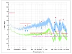
When the signal-to-noise ratio is only a few decibels, the signal can be measured, but the accuracy of the measured signal decreases and the measurement uncertainty increases. The table below is from an online article published by Benz on September 22, 2016 titled "Low signal-to-noise measurements: too close to the noise."
“Reminder: swipe tables left and right”Summary:
Here has been a complete description of how to calculate the dynamic range of the current method test based on the DNAL data of the spectrum analyzer, and it can be seen that the RBW setting of the spectrum analyzer will have an impact on the accuracy and measurement error of the whole test result. So we should learn and apply the above method to complete the standard conducted emission test and improve the signal-to-noise ratio of spectrum analyzer and current probe measurement.
 How to Improve the Signal-to-Noise Ratio of FCC Current Probes
 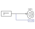 How do I ensure repeatability in measuring common mode currents in cables?
  FCC Current Probe Test Use and Calibration Instructions