
Introduction:
When using the FCC current probe for common-mode conduction current (CE) measurements, we need to pay special attention to the signal-to-noise ratio of the entire test system if very small common-mode currents are being measured, because the FCC current probe is connected to the receiver (spectrum analyzermaybeEMI Receiver) Both devices carry different noise during RF current measurements, which can seriously affect the accuracy of test results. This article will focus on the factors and solutions on how to improve the signal-to-noise ratio of FCC current probes.
Factors affecting the signal-to-noise ratio of current probes:
All FCC-produced current probes are broadband in nature, so they are all capable of responding to a variety of frequency requirements simultaneously. Response signals include intentional signals (intentional operating signals present on the wire/cable under test), unintentional signals (e.g., conducted common mode currents), and noise (e.g., noise coupled to a radiated source near the wire/cable under test). The ability to correctly measure common mode currents at a given frequency in a noisy environment using an FCC current probe depends on the following three factors:
Spectrum analyzer (or receiver)
- Resolution bandwidth (RBW) setting used
- SA noise floor associated with the RBW used (average)
Reference reading:How to improve the signal-to-noise ratio of a spectrum analyzer?
Signal and noise characteristics of the wire/cable under test
- Ambient noise on the wire/cable under test when the wire/cable is not energized
- "System" noise (including CM CE currents), when the wire/cable
- Energize the equipment under test
- Other intentional/unintentional signals on wires/cables
Reference reading:How to ensure repeatability of common mode current measurements on the cable under measurement?
Impedance of current probes at different measurement frequencies
- Transfer impedance (ZT) (sometimes called transfer impedance)
Any conducted common mode (CE-CM) currents present in the wire/cable under test will be picked up and transmitted by the FCC current probe. These currents include those generated by the DUT and those induced from nearby EMF sources (ambient noise), so the currents at the output of the current probe are equal to the sum of the above two types of currents, which are ultimately converted to voltages by the current probe's transmission impedance, Zt, and displayed on a spectrum analyzer. analyzer.
How to improve the signal-to-noise ratio of FCC current probes:
It is clear from the above thatFCC Current ProbeWill only be affected by its own transmission impedance, so as long as the cable under test has an interfering signal, without considering the spectrum analyzer and the cable under test, according to the I = U/R, we just need to choose the current probe with smaller transmission impedance, we can get a larger output signal, when the current probe output signal is much larger than the spectrum analyzer's bottom noise, we don't need to consider the signal-to-noise ratio of the current probe during the test. Impact of the signal-to-noise ratio during the current probe test.
However, in the actual current probe shopping process, FCC current probes with lower transmission impedance generally have a higher unit price, so it is still necessary to balance the purchasing budget with the actual usage needs. We have compiled a full catalog of FCC current probes, which shows all probe models and transmission impedance comparisons in a table comparison.
Case Notes:
When measuring the conducted current method of testing required by the CISPR25 standard, we generally use the FCC current probes distributed by EUTTEST. F-52B, its transfer impedance is shown below:
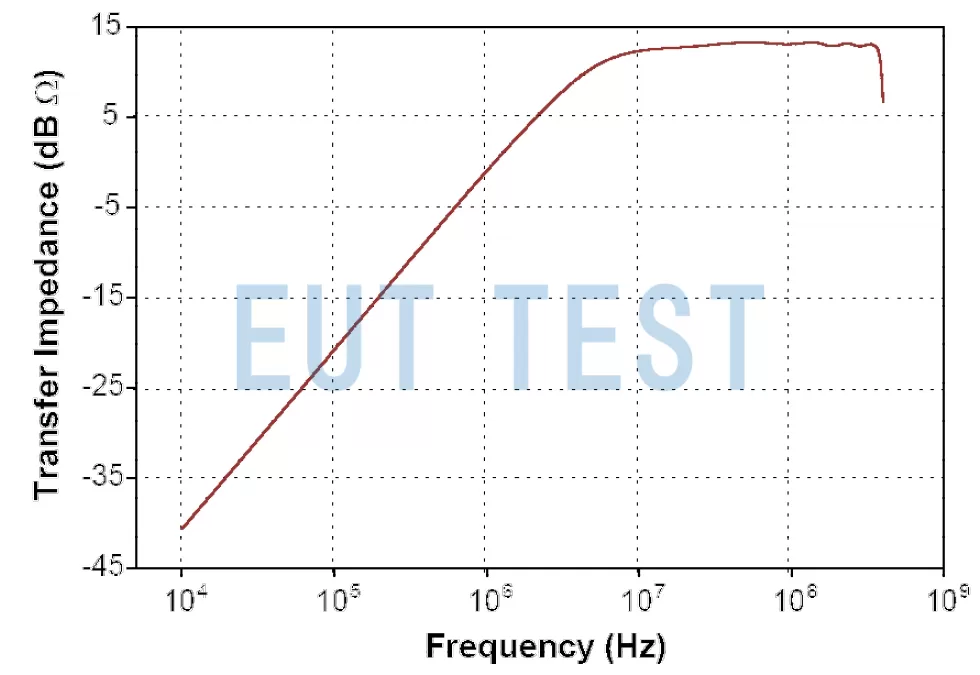
Transfer Impedance Zt of FCC Current Probe F-52B
The nominal use frequency of F-52B is 10kHz-400MHz, from the figure we can get its transfer impedance is -20dBΩ ~ 15dBΩ , we can see that it is nonlinear in the whole available frequency range, when the transfer impedance is the largest 15dBΩ, we will be able to get a very small current probe output current, on the contrary when the transfer impedance is the smallest -20dBΩ we can get a very large output current. From the previous analysis, that is, when the transfer impedance is small, the output signal is large, you can basically do not have to consider the impact of the signal-to-noise ratio, but when the transfer impedance becomes large, the output signal is small, we have to consider whether the output signal to meet the test requirements, because the CISPR25 standard level 5 limit line at high frequencies is very low.
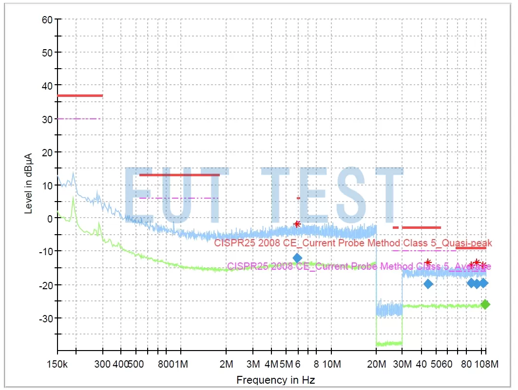
CISPR25 Current Law Class 5 requires very low noise floor
The transfer impedance of the current probe is fixed and you can't do anything to modify it. So eventually we will have to return to considering all three factors affecting the signal-to-noise ratio of the current probe at the same time to address the effects during high-frequency measurements. The solution to the other two factors is explained in detail in the reference at the top of the reference door, so we will not repeat the list here.
Summary:
In the previous section, we explained that improving the signal-to-noise ratio of FCC current probes is simple, but as stated in the opening paragraph, a common-mode current test system is composed of multiple devices, and we still need to take into account the characteristics of the spectrum analyzer as well as the characteristics of the sample under test and optimize them all in order to perform the standard CE current method test on the sample under test, and ultimately pass the product certification and other requirements.
 FCC Current Probe Test Use and Calibration Instructions