
Introduction:
This article is the third part of EUTTEST's compilation of commonly used devices for EMC modification. Ferrite magnetic rings or beads can be used for IO cables, AC and DC power cables, and all the connecting wires on PCB boards. Ferrite rings or beads are made of ferrite, so let's first understand the production process of ferrite and magnetic permeability and other related concepts introduced.
Permeability and flux density of ferrites:
Ferrite is a ferrous magnetic material with a cubic lattice structure. Its manufacturing process and mechanical properties are similar to those of ceramics, and its color is gray-black. For ferrite for electromagnetic interference suppression, the most important performance parameters are magnetic permeability μ and saturation flux density Bs.
- Magnetic permeability in vacuum μ0 = 4π * 10^(-7) H/m.
- Relative permeability μr = μ/μ0 for various materials;
If we categorize common ferrite magnetic media, we call those with μr > 1 paramagnetic; those with μr < 1 antimagnetic; and those with μr much greater than 1 ferromagnetic. The μr of paramagnetic and antimagnetic masses tends to 1 (relative to ferromagnetic masses).
- Common paramagnetic substances: oxygen, aluminum, tungsten, platinum, chromium
- Common antimagnetic substances: nitrogen, water, copper, silver, gold
- Common ferromagnetic materials: iron, cobalt, nickel
The permeability μ can be expressed as a complex number, with the real part constituting the inductance and the imaginary part representing the losses, which increase with frequency. Thus, its equivalent circuit is a series circuit consisting of an inductor L and a resistor R. Both L and R are functions of frequency.
For example, a ferrite with a permeability of 850 has an impedance of less than 10 Ω at 10 MHz and greater than 100 Ω over l00 MHz, which greatly attenuates high-frequency interference. In this way, it constitutes a low-pass filter. Low-frequency R is very small, L plays a major role, electromagnetic interference is reflected and suppressed; high-frequency R increases, electromagnetic interference is absorbed and converted into heat.
Saturation current of ferrite:
Also, once permeability and flux density are understood, we need to pay attention to the saturation current of the ferrite, paying close attention to the fact that it should not be used beyond the maximum saturation current of the component.
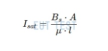
Saturation current of a ferrite ring or bead
- I sat is the saturation current of the ferrite.
- Bs is the saturation flux density of the ferrite.
- A is the cross-sectional area of the ferrite.
- μ is the permeability of the ferrite.
- l is the average loop length of the ferrite
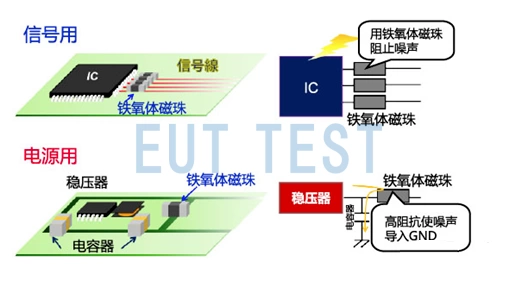
Ferrite suppression elements are widely used on printed circuit boards, power lines and data lines. For example, by adding a ferrite suppression element to the inlet end of the power line of a printed circuit board, high-frequency interference can be filtered out. Ferrite magnetic ring or bead dedicated to inhibit signal lines, power lines on the high-frequency interference and spike interference, it also has the ability to absorb electrostatic discharge pulse interference.
Extended Reading:Two Effective Methods for Suppressing EMI InterferenceThe
Introduction to magnetic rings or beads:
Ferrite components such as magnetic rings or beads suppress high frequency noise and are usually made from a mixture of ferromagnetic oxides such as iron, nickel and zinc, so we can also call them ferrite beads or rings. Because these materials have high permeability and very high equivalent resistance, so they can be connected in series on the signal or power lines of the PCB. In addition, in order to avoid external EMI interference to rectify the test results, we recommend that the PCB under test and all ferrite components be placed in theESA1 set Development of in-shield testing.
Connect ferrite toroids or beads in series on the signal or power lines of the PCBs
From the following graph of impedance characteristics with frequency, we know that when RF current flows through the bead, the low frequency current can pass directly through the ferrite element, but the high frequency current is lost and emitted through heat because of the high frequency impedance characteristics.
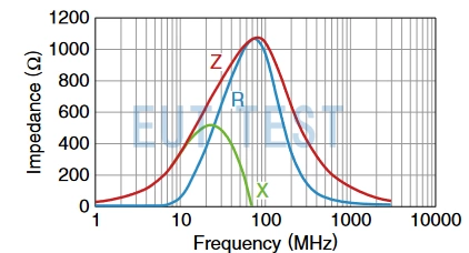
Impedance characteristics of ferrite elements such as magnetic rings or beads as a function of frequency
How to choose the right ferrite components to suppress EMC interference?
We should first complete theStandard conducted or radiated testsThen add a ferrite ring or bead and perform the standard EMC test again, get a test result again, and finally compare the difference between the two test results to see if the rectification is effective.
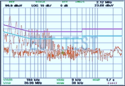
Comparison of test results before and after adding ferrite rings or beads
Here are some lessons learned that different ferrite suppression elements have different optimum suppression frequency ranges. Usually the higher the permeability, the lower the frequency of suppression. In addition, the larger the volume of the ferrite, the better the suppression. For a given volume, a long, thin shape is better than a short, thick one, and the smaller the inner diameter, the better the suppression. But in the case of DC or AC bias current, there is also the problem of ferrite saturation, the larger the cross-section of the suppression element, the less likely to be saturated, can withstand the bias current is greater. The ferrite suppression element should be installed close to the source of the interference. For input/output circuits, it should be as close as possible to the inlet and outlet of the shielding shell. It should also be noted that ferrite components are fragile and should be reliably fixed.
Conclusion:
There is also a wide range of components that can be used for EMC rectification, you can click on the following links for more information.
- EMC rectification commonly used devices - Part I - capacitors
- EMC rectification commonly used devices - Part II - Inductors
- EMC rectification commonly used devices - Part III - ferrite magnetic rings and beads (this article)
- EMC rectification commonly used devices - Part IV - electromagnetic shielding film patch
- EMC rectification commonly used devices - Part V - copper and aluminum foils
- EMC rectification commonly used devices - Part VI - copper braid and grounding wire
- EMC rectification commonly used devices - Part VI - conductive paint and metal sheet