
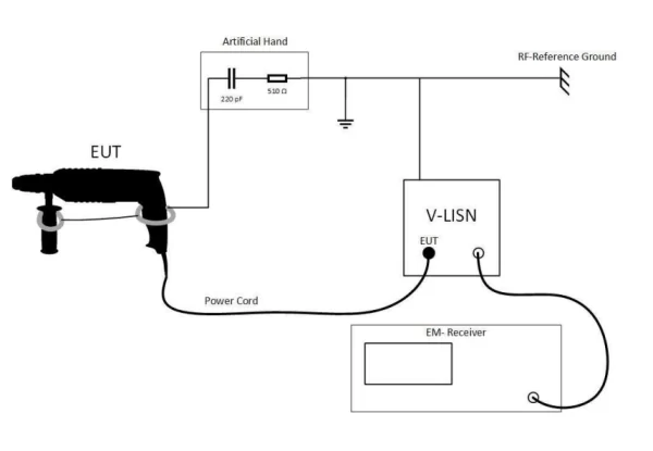
Introduction:
A simulated hand is a type of test instrument mentioned in IEC/CISPR 16-1-2 and GB/T 6113.102,EMCThe industry also refers to this as a “simulated hand.” Standard requirements: For EUTs that are not connected to ground via their metal parts and are intended to be held in the hand during normal use, a simulated hand must be used. A simulated hand may also be required for plastic enclosures with a metal coating. The simulated hand is used in conducted emission tests in the 150 kHz to 30 MHz frequency range (with 5 MHz to 30 MHz being the most critical frequencies) to simulate the influence of the operator’s hand on the measurement. Equipment types requiring evaluation with a simulated hand include power tools, household appliances (such as handheld mixers), telephone handsets, joysticks, keyboards, and other household electronic products.
Structural Composition of the Analog Hand and RC Components:
When conducting conducted emission measurements on handheld household appliances using a simulated hand, a metal foil and an RC network component are required to form the complete simulated hand structure, which must be placed or wrapped around the device in the prescribed manner—typically on parts that the user’s hand is likely to come into contact with when using the appliance.
Metal foil:
The metal foil strip used to simulate the effect of the user’s hand on a device’s controller or body is typically 60 mm wide. For keyboards, a single strip of metal foil may be used, or, more preferably, a metal plate with maximum dimensions of 100 mm × 300 mm may be placed on top of the keyboard.
RC components:
The metal foil must be connected to the reference point of the interference measurement system in the specified manner using an RC element consisting of a capacitor (C = 220 pF ± 20%) in series with a resistor (510 Ω ± 10%), as shown at point a in the figure below. If the equipment enclosure is made of insulating material, the metal foil shall be wrapped around handle B [Figures b) and c)] and the second handle D (if present). A 60 mm wide strip of metal foil shall also be wrapped around the motor stator core at position C [Figures b) and c)], or around the gearbox (if this results in a higher interference level). All of this metal foil (including the metal ring or sleeve A, if applicable) should be connected together to the M terminal of the RC component.
If part of the equipment housing is made of metal and another part is made of insulating material and serves as an insulated handle, metal foil should be wrapped around points B and D [Fig. b]. If the motor housing is non-metallic, wrap 60 mm wide metal foil around section C of the housing at the motor stator core; or wrap it around the gearbox (if it is made of insulating load-bearing material and a higher level of interference is measured). Connect the metal part A of the chassis, the metal foil wrapped around handles B and D, and the metal foil at point C on the chassis, and then connect this assembly to terminal M of the RC element.
When a Class II device (i.e., double-insulated, without a ground wire) has two insulated handles, A and B, and a metal housing, C—such as a chainsaw [Fig. c)]—metal foil should be wrapped around handles A and B. After connecting the metal foil at points A and B to the metal housing C, connect it to the M terminal of the RC component.
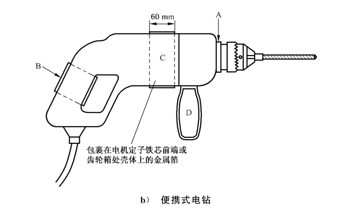
How to Install a Simulated Hand on a Power Tool
For the telephone handset, a 60-mm-wide metal foil is wrapped around the handset with some overlap. For the keypad, the metal foil or printed circuit board should cover the entire key area as much as possible. When using a printed circuit board, the metal side must be placed on the keypad, but its dimensions must not exceed 300 mm × 100 mm.
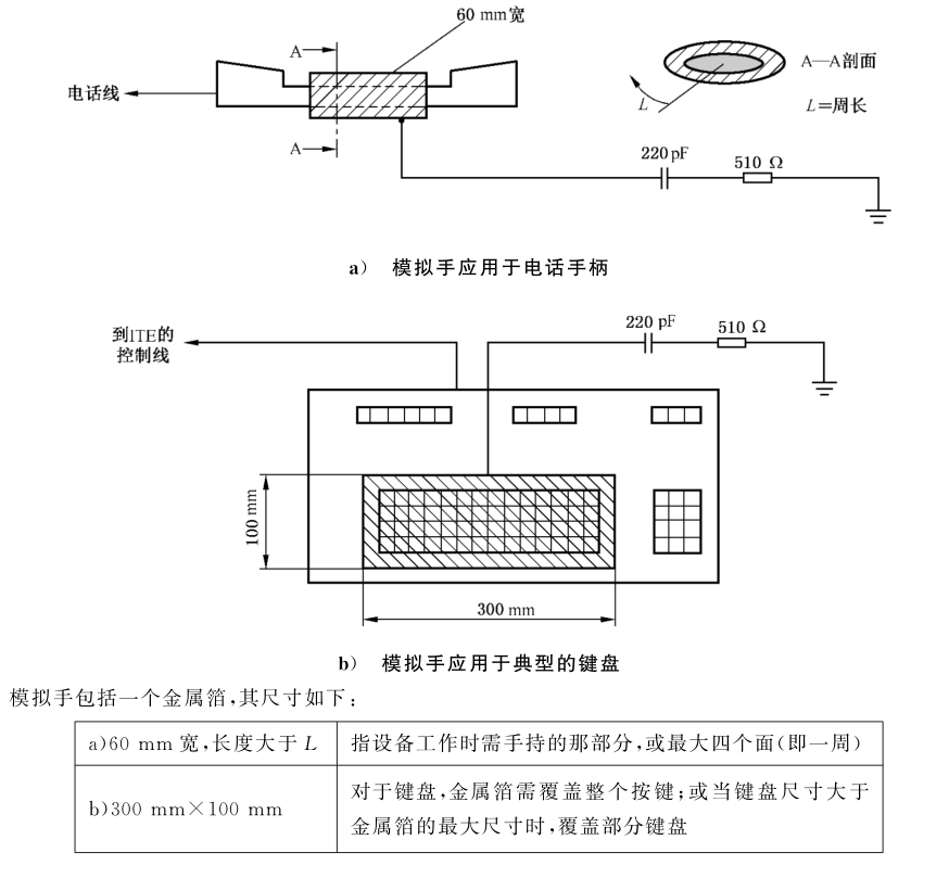
How to Attach the Telephone Handset and Keypad to a Mannequin
The simulated hand consists of a metal foil with the following dimensions:
“Reminder: swipe tables left and right”When the metal foil is at its maximum size, it covers part of the keyboard.
The length of the connecting wire between the RC component and the metal foil should be 1 m. If the test setup requires a longer connecting wire, the total inductance of the wire must be less than 1.4 μH when the measurement frequency is close to 30 MHz.
Calculating Cable Diameter:
When the entire interconnect is treated as a single wire in free space, and the upper limit frequency for conducted emission testing is 30 MHz, the inductance L of the interconnect should be less than 1.4 μH. When the inductance meets the 1.4 μH requirement, the impedance of the RC network will become the dominant factor at 30 MHz.

Formula for Calculating the Minimum Diameter of a Connecting Cable
μ: permittivity, 4π × 10⁻⁷ H/m; ;
l: Line length (specified length), in meters (m);
d: The diameter of the wire, in meters (m).
For example, when the cable length is 1 meter, μ = 4π × 10⁻⁷ H/m, and e ≈ 2.71828, then according to the formula above, the minimum diameter (m) of the cable is calculated as d = 0.00134185 m = 1.34185 mm. This means the minimum diameter of the cable you use should not be less than 1.34185 mm (when the cable is 1 meter long). If using a different length, please recalculate as required.
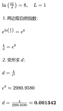
ln Logarithm Calculation Process
Product Recommendation:
If your product falls into one of the above categories, you should consider purchasing a test fixture to ensure that your tests meet EMC standards. We recommend usingSchwarzbeck's Simulated Handrespond in singingV-LISN, then useR&S EMI ReceiverMeasure the conducted disturbance components on the product's power cord.
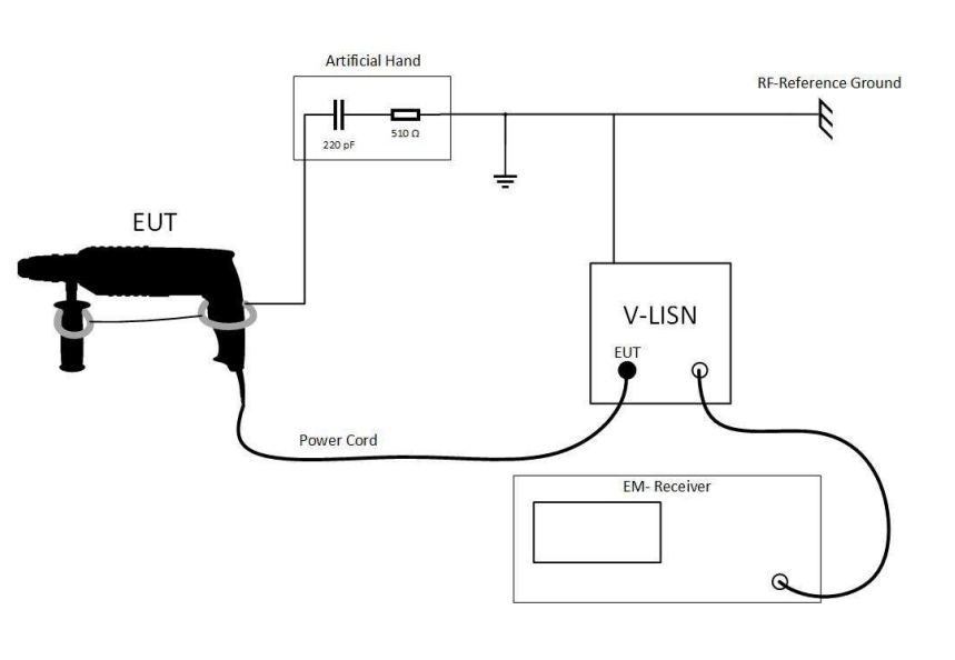
A typical test system consisting of an analog hand, a V-LISN, and an EMI receiver
 EMC Sources and Differences between Conducted and Radiated EMI
  What are the EMC test equipment