
Introduction:
Until now, EMC AC conducted emissions from PV inverters connected to grid terminals have typically been measured according to the CISPR 16-1-2 standard and using a dedicated V-LISN. However, PV inverters may cause ripple currents on the DC output side of the inverter, which are mostly proportional to the power supply frequency, through the cables and PV generator modules and can radiate externally as a magnetic field, and these disturbances can have a noticeable interfering effect on a number of electronic products. However, conventional measurements at the AC terminals of a PV inverter will not reveal this interference phenomenon.
Thus, a new DC artificial network, DC AN, has been introduced, dedicated to the measurement of conducted disturbances at the DC port of PV inverters. In order to adapt the product to the needs of PV inverters, the device under test has to be connected to the wing terminals on the front panel of the DC AN, with the PV generator or PV simulator connected to the rear side of the DC AN. According to the circuit schematic below, capacitor C3 is limited to 0.22 µF to avoid interference to the EUT, which also results in a differential mode decoupling of more than 20 dB, if a higher decoupling value is required (e.g. 40 dB or higher), an additional 0.1 µF/1500 V DC capacitor can be used at the AE terminal.
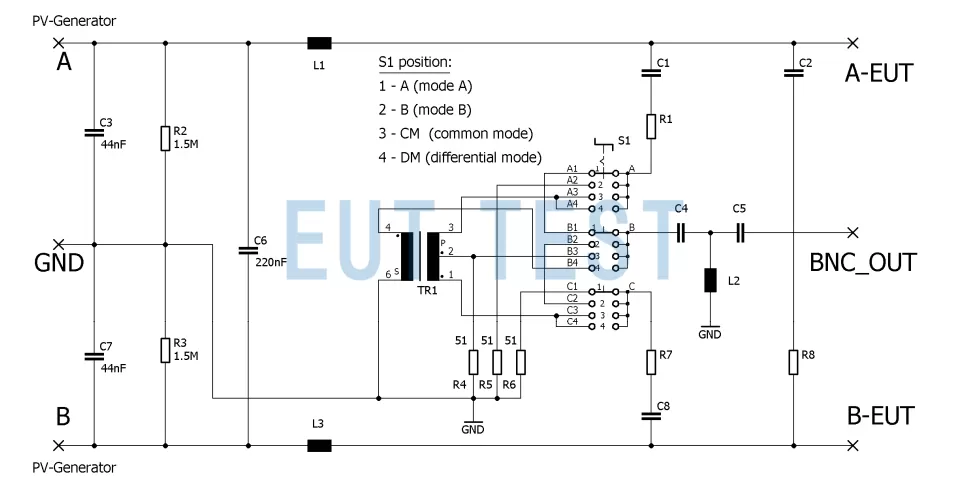
Circuit schematic diagram of DC artificial network DC AN
PVDC DC artificial network selection:
The schwarzbeck symmetrical DC PVDC serial LISN, marketed by EUTTEST, can be used to measure disturbance voltages on the DC side of photovoltaic inverters in the frequency range from 0.15 MHz to 30 MHz. the PVDC LISN is designed with an air core or an ironless inductor to prevent intermodulation. The allowable continuous current is 100 A (with fan enabled). A continuous current of 50 A can be supplied without a fan. Short-time currents in excess of 150 A may be applied. The temperature of the built-in sensor must not exceed 150°C. The device under test is connected to the wing terminals on the front panel. The PV generator or PV simulator is connected to the rear side.
Depending on the rated current of the PV inverter, the following four models of DC-AN are now available:
“Reminder: swipe tables left and right”As shown in the figure below, we generally recommend our customers to select the appropriate DC artificial network based on the maximum continuous current and maximum short-time current of their self-produced products.

Selection of DC artificial networks for PV inverters based on maximum continuous and maximum short-time currents
How do I test for conducted interference emissions using the DC-AN?

Measurement of DC Port Conducted Interference Emission Configuration of PV Inverter using PVDC LISN
- The PV generator or simulator must be connected to the rear panel AE port on the PVDC LISN (AE).
- The DC input of the Equipment Under Test (EUT), i.e. the PV inverter, is connected to the front panel terminals.
- The RFI voltage from the DC side of the inverter is measured at the "output" BNC socket, which can be connected to a 50Ω EMI receiver.
- The switches on the front panel must be set to "DM Differential Mode", "CM Common Mode", "A" or "B" depending on the desired measurement mode. ".
- Mode A or Mode B: Asymmetrical interference voltage is measured from port "A" or "B" to RF ground (V-LISN).
- Common Mode (CM): The sum of the interference voltages at ports "A" and "B" is measured with respect to RF ground (T-LISN, asymmetrical interference voltage). In all three measurement modes, the input impedance seen from the device under test is 150Ω.
- Differential mode (DM): Measurement of the symmetrical interference voltage (Delta LISN) between terminals "A" and "B". The impedance is 150 Ω. The RF ground potential is connected via the GND connector or the aluminum strip on the rear panel.
Caveats:
We provide every customer who purchases instrumentation from EUTTEST with a safety instruction document, and in the event that your document is lost, you can also briefly refer to the following Measurement of Conducted Interference Emissions from Photovoltaic Inverters using the PVDC LISN.
- In any case, properly connect the ground port for the LISN and ground it nearby before connecting it to the power cord.
- Improper use of the LISN may result in fatal injury! Always disconnect the supply voltage before connecting or disconnecting the terminals.
- There must be an easily accessible circuit breaker before and after the LISN!
- LISN's capacitors can store charge for long periods of time, even if LISN is completely disconnected from the power source and equipment.
- We strongly recommend discharging the capacitor to ground via an insulated cable before touching the terminals.
- Technically, a discharge resistor cannot be used because the vast majority of GCPCs (Grid Connected Power Conditioners) test multiple insulation conditions during startup.
- Air circulation in the test environment must be maintained.
- Neither the top nor the bottom of the LISN can be covered during operation!
Summary:
Above is a brief introduction to the measurement of conducted interference at the DC port of a PV inverter, you can learn that the conducted interference of a PV inverter needs to be measured at both the AC and DC ports, and that the DC port needs a special DC-AN, and that you can also choose different models of DC artificial networks according to the different EUT currents.
 EMC Test Program Introduction